


ADSP-21369 EZ-KIT Lite Evaluation System Manual 1-11
Using EZ-KIT Lite
Two of the general-purpose push buttons are attached to the
FLAG pins of
the processor, while the other two are attached to the DAI pins. All of the
push buttons connect to the processor through a DIP switch. The DIP
switch allows processor pins, which connect to the push buttons, to be dis-
connected. See “Push Button Enable Switch (SW7)” on page 2-12 for
instructions on how to disable the push buttons from driving the corre-
sponding processor pin.
The state of the push buttons, connected to the
FLAG pins, can be deter-
mined by reading the
FLAG register. The push buttons connected to the
DAI pins must be configured as interrupts. It is necessary to set up an
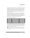
interrupt routine to determine each pin’s state. Table 1-2 shows how each
push button connects to the processor. Refer to the related example pro-
gram shipped with the EZ-KIT Lite for more information.
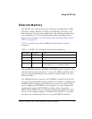
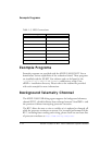
Table 1-3 summarizes the LED connections to the processor. In order to
use the LEDs connected to the DAI or DPI, the respective registers inside
the processor must be correctly configured. For more information on how
to program the pins, refer to the ADSP-2136x SHARC Processor Hardware
Reference for ADSP-21367/8/9 Processors.
L
An example program is included in the EZ-KIT Lite installation
directory to demonstrate the functionality of the LEDs and push
buttons.
Table 1-2. Push Button Connections
Push Button Label Push Button Reference Designator Processor Pin
PB1 SW8 FLAG1/~IRQ1
PB2 SW11 FLAG0/~IRQ0
PB3 SW10 DAI19
PB4 SW9 DAI20