


LEDs and Push Buttons
2-16 ADSP-21369 EZ-KIT Lite Evaluation System Manual
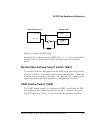
USB Monitor LED (LED11)
The USB monitor LED (LED11) indicates that USB communication has
been initialized successfully, and you can connect to the processor using a
VisualDSP++ EZ-KIT Lite session. Once the USB cable is plugged into
the board, it takes approximately 15 seconds for the USB monitor LED to
light. If the LED does not light, try cycling power on the board and/or
reinstalling the USB driver (see the VisualDSP++ Installation Quick Refer-
ence Card).
L
When VisualDSP++ is actively communicating with the EZ-KIT
Lite target board, the LED can flicker, indicating communications
handshake.
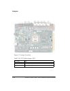
Push Buttons (SW8–11)
Four push buttons (SW8–11) are provided for general-purpose user input.
Two of the push buttons connect to the
FLAG pins of the processor. The
other two connect to the DAI of the processor. The push buttons are
active
HIGH and, when pressed, send a High (1) to the processor. Refer to
“LEDs and Push Buttons” on page 1-10 for more information. The push
button enable switch (
SW7) is capable of disconnecting the push buttons
from the corresponding processor pin (refer to “Push Button Enable
Switch (SW7)” on page 2-12 for more information).
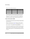
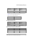
The push buttons and corresponding processor signals summarized in
Table 2-9.
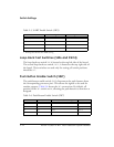
Table 2-9. Push Button Connections
Push Button Label Push Button Reference Designator Processor Pin
PB1 SW8 FLAG1/~IRQ
PB2 SW11 FLAG0/~IRQ0