


LEDs and Push Buttons
2-14 ADSP-21369 EZ-KIT Lite Evaluation System Manual
LEDs and Push Buttons
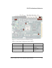
This section describes the functionality of the LEDs and push buttons.
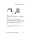
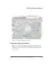
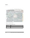
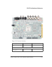
Figure 2-6 shows the LED and push button locations.
General Purpose LEDs (LED1–8)
There are eight general-purpose LEDs on the board. Five LEDs connect to
the DPI interface, two LEDs connect to the DAI interface, and one LED
connects to
FLAG3 of the processor. “LEDs and Push Buttons” on
page 1-10 summarizes the LED connections. In order to use the LEDs
connected to the DAI or DPI, the respective registers inside the processor
must be correctly configured. For more information on how to program
the pins, refer to the ADSP-2136x SHARC Processor Hardware Reference
for ADSP-21367/8/9 Processors.
Power LED (LED9)
When LED9 is lit (green), it indicates that power is being properly supplied
to the board.
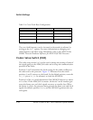
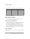
Table 2-8. ELVIS Function Generator Configuration Switch (SW13)
Channel Switch Position Audio Signal
AMP_LEFT_IN
1 (ON
1
)
LEFT_IN
AMP_RIGHT_IN
2 (ON) RIGHT_IN
AMP_LEFT_IN
3 (OFF) DAC0
AMP_RIGHT_IN
4 (OFF) DAC1
AMP_LEFT_IN
5 (OFF) FUNCT_OUT
AMP_RIGHT_IN
6 (OFF) FUNCT_OUT
1 Bold typeface denotes the default settings.