


System Architecture
2-6 ADSP-21369 EZ-KIT Lite Evaluation System Manual
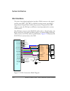
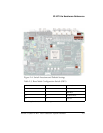
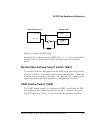
Figure 2-3 illustrates the EZ-KIT Lite’s connections to the DPI. The DPI
pins connect to the SPI flash memory, the SPI interface of the AD1835A
codec, a UART, a 20-pin header, and five LEDs.
To use the DPI for a different purpose, disable any signal driving the DPI
pins with a switch (see “UART Enable Switch (SW5)” on page 2-11). Any
DPI pin connected to an LED can be used without having to disconnect
the pin. You can, however, see the respective LED turn
ON and OFF when
using the signal for other purposes.
All of the DPI signals are available externally via the expansion interface
connectors (
J3–1), as well as the 0.1” spaced header P3. The pinout of
these connectors can be found in “Schematics” on page B-1.
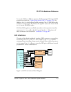
FLAG Pins
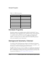
The processor has four general-purpose IO flag pins. Table 2-1 describes
the flag connections.
For information on how to disable the push buttons from driving the cor-
responding processor flag pin, see “Push Button Enable Switch (SW7)” on
page 2-12.
The
FLAG signals are available externally via the expansion interface con-
nectors (
J3–1). The pinout of these connectors can be found in
“Schematics” on page B-1.
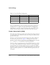
Table 2-1. IO FLAG Pins
FLAG Pin EZ-KIT Lite Function
FLAG0 Push button (SW2) input
FLAG1 Push button (SW2) input
FLAG2 SDRAM chip select
FLAG3 LED8