


ADSP-21369 EZ-KIT Lite Evaluation System Manual 2-7
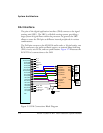
EZ-KIT Lite Hardware Reference
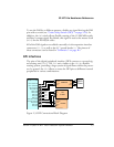
External PLL
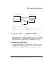
The ADSP-21369 EZ-KIT Lite contains an external phase lock loop to
help generate a faster and more stable master input clock
MCLK. The PLL
uses DAI pin 3 as an input clock from the ADSP-21369 processor. The
new clock generated by PLL connects to the processor via DAI pin 2.
Example programs are included in the EZ-KIT Lite installation directory
to demonstrate how to configure and use the board’s external PLL.
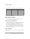
Expansion Interface
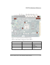
The expansion interface consists of the three 90-pin connectors. Table 2-2
shows the interfaces each connector provides. For the exact pinout of these
connectors, refer to “Schematics” on page B-1. The mechanical dimen-
sions of the connectors can be obtained from Technical or Customer
Support.
Limits to the current and to the interface speed must be taken into consid-
eration when using the expansion interface. The maximum current limit is
dependent on the capabilities of the used regulator. Additional circuitry
can also add extra loading to signals, decreasing their maximum effective
speed.
[
Analog Devices does not support and is not responsible for the
effects of additional circuitry.
Table 2-2. Expansion Interface Connectors
Connector Interfaces
J1 5V, ADDR[23–0], DATA[31–0]
J2
3.3V, FLAG[3–0], DAIP[20–1], DPI[14–1], SDRAM control signals
J3 5V, 3.3V, reset, parallel port control signals