


ELVIS Interface
1-8 ADSP-21369 EZ-KIT Lite Evaluation System Manual
The SPI flash memory connects to the SPI port of the processor and
designates:
• DPI pin 5 (
DPI5) as a chip select
• DPI pin 3 (
DPI3) as the SPI clock
• DPI pin 1 (
DPI1) as the MOSI
• DPI pin 2 (DPI2) as the MISO.
By default, the DPI is setup for the SPI flash, and any required changes to
the SPI flash can be made by modifying the DPI of the processor. An
example program is included in the EZ-KIT Lite installation directory to
demonstrate how to read and write to the SPI flash memory.
The asynchronous SRAM memory and the parallel flash memory connect
to the asynchronous memory controller of the processor. Each of their
respective memory banks can be independently programmed with differ-
ent timing parameters. For more information on changing wait states to
speed up or slow down the asynchronous controller and other setup infor-
mation, refer to the ADSP-2136x SHARC Processor Hardware Reference for
ADSP-21367/8/9 Processors. Example programs are included in the
EZ-KIT Lite installation directory to demonstrate how to read and write
to the SRAM or flash memory.
ELVIS Interface
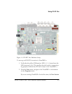
The ADSP-21369 EZ-KIT Lite board contains the National Instruments
Educational Laboratory Virtual Instrumentation Suite interface. The
interface features the DC voltage and current measurement modules,
oscilloscope and bode analyzer modules, function generator, arbitrary
waveform generator, and digital IO.