


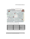

ADSP-21369 EZ-KIT Lite Evaluation System Manual 2-13
EZ-KIT Lite Hardware Reference
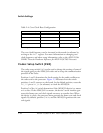
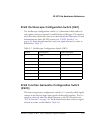
ELVIS Oscilloscope Configuration Switch (SW1)
The oscilloscope configuration switch (SW1) determines which audio cir-
cuit signals connect to channels A and B of the oscilloscope. The switch is
used only when the board connects to the Educational Laboratory Virtual
Instrumentation Suite (ELVIS) station (see “ELVIS Interface” on
page 1-8). Each channel must have only one signal selected at a time, as
described in Table 2-7.
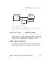
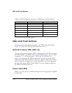
ELVIS Function Generator Configuration Switch
(SW13)
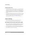
The function generator configuration switch (SW13) controls which signals
connect to the left and right input signals of the audio interface. The
SW13
switch is used only when the board connects to the ELVIS station (see
“ELVIS Interface” on page 1-8). Each channel must have only one signal
selected at a time, as described in Table 2-8.
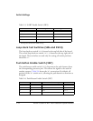
Table 2-7. Oscilloscope Configuration Switch (SW1)
Channel Switch Position Audio Circuit Signal
A
1 (OFF
1
)
1 Bold typeface denotes the default settings.
AMP_LEFT_IN
A2 (OFF) AMP_RIGHT_IN
A3 (OFF) LEFT_OUT
A4 (OFF) RIGHT_OUT
B5 (OFF) AMP_LEFT_IN
B6 (OFF) AMP_RIGHT_IN
B7 (OFF) LEFT_OUT
B8 (OFF) RIGHT_OUT