


Switch Settings
2-10 ADSP-21369 EZ-KIT Lite Evaluation System Manual
The core clock frequency can be increased or decreased via software by
writing to the
PMCTL register. For more information on changing core
clock frequency and other setup information, refer to the ADSP-2136x
SHARC Processor Hardware Reference for ADSP-21367/8/9 Processors.
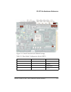
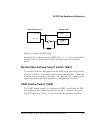
Codec Setup Switch (SW3)
The codec setup switch (SW3) can be used to change the routing of some of
the signals going to the AD1835A codec and to setup the communication
protocol of the codec.
Positions 1 and 2 determine the clock routing for the audio oscillator to
the codec and to the processor. Figure 2-5 illustrates how the switch
positions 1 and 2 connect on the board. In the default position, route the
DAI_P17 pin to DAI_P6 (in software) to clock the AD1835A.
Position 3 of the SW3 switch determines if the AD1835A device is a master
or is a slave. If the AD1835A is a master, the device’s serial interface gen-
erates the frame sync and clock signals necessary to transfer data. When
the device is a slave, the processor must generate the frame sync and clock
signals. By default, position 3 is
ON, and the AD1835A generates the con-
trol signals.
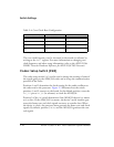
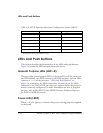
Table 2-4. Core Clock Rate Configuration
CLKCFG1 (Position 3) CLKCFG0 (Position 4) Core to CLKIN Ratio
ON ON 6:1
ON OFF
16:1
1
OFF ON 32:1
OFF
OFF
Reserved
1 Bold typeface denotes the default ratio.