


Switch Settings
2-8 ADSP-21369 EZ-KIT Lite Evaluation System Manual
JTAG Emulation Port
The JTAG emulation port allows an emulator to access the internal and
external memory of the processor through a 6-pin interface. The JTAG
emulation port of the processor also connects to the USB debugging inter-
face. When an emulator connects to the board at
P2, the USB debugging
interface is disabled. This is not the standard connection of the JTAG
interface.
For information about the standard connection of the interface, see EE-68
published on the Analog Devices Web site. For more information about
the JTAG connector, see “JTAG Header (P2)” on page 2-25. To learn
more about available emulators, go to Analog Devices Web site:
http://www.analog.com/processors/resources/crosscore/emula-
tors/index.html
.
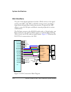
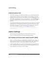
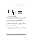
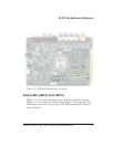
Switch Settings
This section describes the function of the EZ-KIT Lite switches.
Figure 2-4 shows the switch locations and default settings.
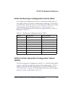
Boot Mode and Clock Ratio Select Switch (SW2)
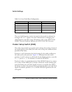
The SW2 switch sets the boot mode and clock multiplier ratio. Table 2-3
shows how to set up the boot mode using positions 1 and 2. By default,
the EZ-KIT Lite boots in external port mode from flash memory.
Table 2-4 shows how to set up the clock multiply ratio using positions 3
and 4. By default, the processor increases the clock multiply ratio by six-
teen, setting the core clock to 393.216 MHz.