S3P8245/P8249 OTP S3C8245/P8245/C8249/P8249
21-6
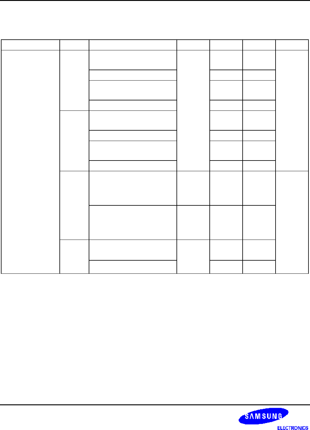
Table 21-4. D.C. Electrical Characteristics (Concluded)
(T
A
= -25
°
C to + 85
°
C, V
DD
= 1.8 V to 5.5 V)
Parameter Symbol Conditions Min Typ Max Unit
Supply current
(1)
I
DD1
(2)
V
DD
= 5 V ± 10 %
10 MHz crystal oscillator
– 12 25 mA
3 MHz crystal oscillator 4 10
V
DD
= 3 V ± 10 %
10 MHz crystal oscillator
3 8
3 MHz crystal oscillator 1 5
I
DD2
Idle mode: V
DD
= 5 V ± 10 %
10 MHz crystal oscillator
3 10
3 MHz crystal oscillator 1.5 4
Idle mode: V
DD
= 3 V ± 10 %
10 MHz crystal oscillator
1.2 3
3 MHz crystal oscillator 0.5 1.5
I
DD3
Sub operating: main-osc stop
V
DD
= 3 V ± 10 %
32.768 kHz crystal oscillator
OSCCON.4 = 1
– 20 40 uA
I
DD4
Sub idle mode: main-osc stop
V
DD
= 3 V ± 10 %
32.768 kHz crystal oscillator
OSCCON.4 = 1
– 7 14
I
DD5
Main stop mode : sub-osc stop
V
DD
= 5 V ± 10 %, T
A
= 25
°
C
– 1 3
V
DD
= 3 V ± 10 %, T
A
= 25
°
C
0.5 2
NOTES:
1. Supply current does not include current drawn through internal pull-up resistors or external output current loads.
2. I
DD
and I
DD2
include a power consumption of subsystem oscillator.
3. I
DD3
and I
DD4
are the current when the main system clock oscillation stop and the subsystem clock is used.
And does not include the LCD, voltage booster, and voltage level detector.
4. I
DD5
is the current when the main and subsystem clock oscillation stop.


