S3C8245/P8245/C8249/P8249 ELECTRICAL DATA
19-5
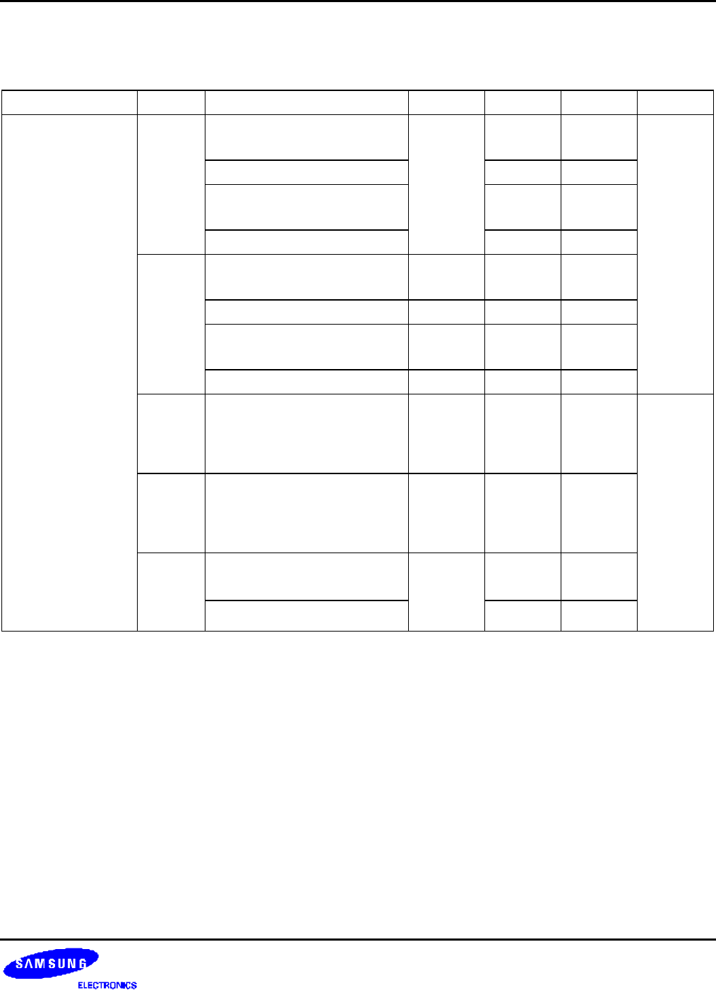
Table 19-2. D.C. Electrical Characteristics (Concluded)
(T
A
= -25
°
C to + 85
°
C, V
DD
= 1.8 V to 5.5 V)
Parameter Symbol Conditions Min Typ Max Unit
Supply current
(1)
I
DD1
(2)
V
DD
= 5 V ± 10 %
10 MHz crystal oscillator
– 12 25 mA
3 MHz crystal oscillator 4 10
V
DD
= 3 V ± 10 %
10 MHz crystal oscillator
3 8
3 MHz crystal oscillator 1 5
I
DD2
Idle mode: V
DD
= 5 V ± 10 %
10 MHz crystal oscillator
– 3 10
3 MHz crystal oscillator 1.5 4
Idle mode: V
DD
= 3 V± 10 %
10 MHz crystal oscillator
1.2 3
3 MHz crystal oscillator 0.5 1.5
I
DD3
Sub operating: main-osc stop
V
DD
= 3 V ± 10 %
32.768 kHz crystal oscillator
OSCCON.4 = 1
– 20 40 uA
I
DD4
Sub idle mode: main-osc stop
V
DD
= 3 V ± 10 %
32.768 kHz crystal oscillator
OSCCON.4 = 1
– 7 14
I
DD5
Main stop mode : sub-osc stop
V
DD
= 5 V ± 10 %, T
A
= 25
°
C
– 1 3
V
DD
= 3 V ± 10 %, T
A
= 25
°
C
0.5 2
NOTES:
1. Supply current does not include current drawn through internal pull-up resistors or external output current loads.
2. I
DD1
and I
DD2
include a power consumption of subsystem oscillator.
3. I
DD3
and I
DD4
are the current when the main system clock oscillation stop and the subsystem clock is used.
And does not include the LCD and Voltage booster and voltage level detector
4. I
DD5
is the current when the main and subsystem clock oscillation stop.


