S3C8245/P8245/C8249/P8249 LCD CONTROLLER/DRIVER
14-7
LCD DRIVE VOLTAGE
The LCD display is turned on only when the voltage difference between the common and segment signals is greater
than V
LCD
. The LCD display is turned off when the difference between the common and segment signal voltages is
less than V
LCD.
The turn-on voltage, + V
LCD
or - V
LCD
, is generated only when both signals are the selected signals
of the bias. Table 14-7 shows LCD drive voltages for static mode, 1/2 bias, and 1/3 bias.
Table 14-6. LCD Drive Voltage Values
LCD Power Supply Static Mode 1/2 Bias 1/3 Bias
V
LC2
V
LCD
V
LCD
V
LCD
V
LC1
– V
LCD
2/3 V
LCD
V
LC0
– 1/2 V
LCD
1/3 V
LCD
V
ss
0 V 0 V 0 V
NOTE: The LCD panel display may deteriorate if a DC voltage is applied that lies between the common and segment
signal voltage. Therefore, always drive the LCD panel with AC voltage.
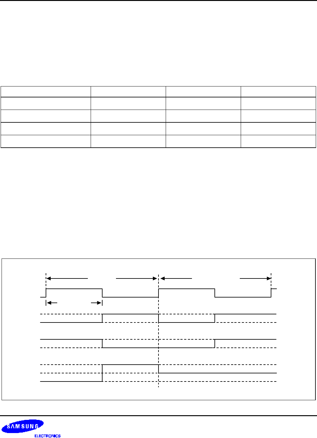
LCD SEG/SEG SIGNALS
The 32 LCD segment signal pins are connected to corresponding display RAM locations at 00H–0FH.
Bits 0-3 (and 4-7) of the display RAM are synchronized with the common signal output pins COM0, COM1, COM2,
and COM3.
When the bit value of a display RAM location is "1", a select signal is sent to the corresponding segment pin. When
the display bit is "0", a 'no-select' signal is sent to the corresponding segment pin. Each bias has select and no-
select signals.
COM-SEG
FR
Select Non-Select
1 Frame
COM
SEG
V
LC2
V
SS
V
LC2
V
SS
V
LC2
V
SS
-V
LC2
Figure 14-4. Select/No-Select Bias Signals in Static Display Mode


