


79
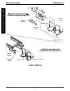
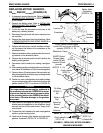
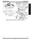
FIGURE 22 - REPLACING MOTOR/GEARBOX -
RANGER II MWD BASIC
Wheelchair Frame
LONG Socket Screws (Apply
Loctite 242 and torque to 60-inch
pounds)
(STEPS 11, 13)
Battery
Tray
Mounting
Bracket
Motor/
Gearbox
Clutch Handle
(STEP 9)
Dust Cover
Hex Bolt
Washer
Crossbrace
Locknut
Pin
(STEP 14)
Detent Ball
Motor/Gearbox
(STEP 14)
DETAIL "B"
Clutch Handle
(STEP 14)
Tie Wrap
(STEPS 3,
20)
STEPS 5, 6 AND 17
Pin
(STEP 8)
SHORT Socket
Screws (Apply
Loctite 242 and
torque to 60-inch
pounds)
(STEPS 11, 13)
Battery Motor
Connectors
(STEPS 4, 19)
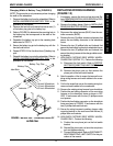
REPLACING MOTOR/GEARBOX -
R2
BASIC
AND R2
250 SERIES
(FIGURE 22)
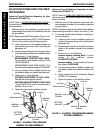
1. If necessary, remove the shrouds. Refer to REMOV-
ING/INSTALLING SHROUDS in PROCEDURE 10
of this manual.
2. Remove the battery boxes. Refer to
INSTALLING/
REMOVING BATTERY BOXES in this procedure of
the manual.
3. Cut the tie wrap that secures the motor wire to the
battery tray mounting bracket.
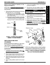
4. Disconnect the right and/or left motor connector from
the controller.
5. Remove the drive wheels from the wheelchair. Refer
to
REMOVING/INSTALLING DRIVE WHEELS in
PROCEDURE 9 of this manual.
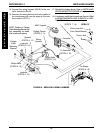
6. Remove the dust covers, hex bolt, washers and lock-
nut that secure the bottom of the crossbrace to the
wheelchair frame
7. Remove the bottom of the crossbrace from the mount-
ing bracket on the wheelchair frame.
8. Remove the pin that secures the clutch handle to the
existing motor/gearbox.
9. Disconnect clutch handle from existing motor/gear-
box.
10. Note mounting position of motor/gearbox on the wheel-
chair frame for installation of the new motor/gearbox.
11. Remove the six (6) socket screws that secure the ex-
isting motor/gearbox and battery tray mounting bracket
to the wheelchair frame.
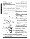
12. Position the new motor/gearbox and existing battery
tray mounting bracket on the wheelchair frame at the
position noted in STEP 10 as shown in FIGURE 22.
CAUTION
The longer socket screws must be positioned in
the mounting holes on the OUTSIDE of the wheel-
chair frame and the short socket screws must be
in the mounting holes on the INSIDE of the wheel-
chair frame. Otherwise damage to the gearbox
may result.
13. Use Loctite 242 and tighten the battery tray mounting
bracket and motor/gearbox to the wheelchair frame
securely with the six (6) socket screws. Torque to 60-
inch pounds.
14. Connect the clutch handle to the new motor/gearbox
and line up the mounting holes.
15. Insert the pin through clutch handle and new motor/
gearbox as shown in DETAIL "B" in FIGURE 22.
MWD WHEELCHAIRS
M
W
D
W
H
E
E
L
C
H
A
I
R
S
PROCEDURE 14