


59
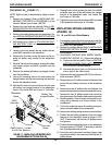
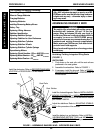
1. Remove the battery boxes. Refer to INSTALLING/
REMOVING BATTERY BOXES in this procedure of
the manual.
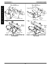
2. Perform one (1) of the following:
A. WHEELCHAIR EQUIPPED WITH FLIP-UP RE-
MOVABLE FOOTBOARD - Remove the hex
screws and spacers that secure the battery tray
hanger bracket and footboard mounting bracket
to the wheelchair frame.
B. WHEELCHAIR NOT EQUIPPED WITH FLIP-UP
REMOVABLE FOOTBOARD - Remove the front
hex screw that secures the battery tray hanger
bracket to the wheelchair frame.
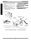
3. Rotate battery tray hanger bracket up.
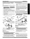
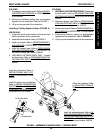
4. Left side of wheelchair only - Remove the front dust
cover from the end of the crossbrace.
NOTE: Left is determined by sitting in the wheelchair.
5. Refer to the charts in this procedure to determine
proper mounting position that corresponds to the user's
weight.
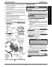
6. Remove the six (6) socket screws that secure the mo-
tor to the wheelchair frame.
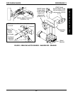
7. Position the motor on the wheelchair frame at the po-
sition noted in STEP 5 as shown in FIGURE 20.
CAUTION
The longer socket screws must be positioned in
the mounting holes on the OUTSIDE of the wheel-
chair frame and the short socket screws must be
in the mounting holes on the INSIDE of the wheel-
chair frame. Otherwise damage to the gearbox
may result.
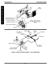
REPOSITIONING MOTORS (FIGURE
20)
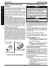
WARNING
The overall performance of the wheelchair WILL
be affected by the front wheel mounting posi-
tion. The following charts show the mounting po-
sition of the motors for each seat width and depth
depending on the factory setting or user's weight.
If the mounting position that corresponds to the
user's weight is different than the factory setting,
the motors MUST BE repositioned to maintain
proper stability and controllability BEFORE using
the wheelchair. Otherwise injury or damage can
occur.
Periodically review the following charts to make
sure the motor mounting position still corresponds
to the user's weight to maintain the proper stabil-
ity and controllability.
R2
JR
ONLY - NEVER reposition the motors. Reposi-
tioning the motors forward WILL reduce the con-
trollability of the wheelchair. This procedure MUST
be performed by an Invacare Dealer.
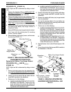
NOTE: If motors are repositioned, the front riggings may
need to be repositioned. Refer to ADJUSTING/REPLAC-
ING TELESCOPING FRONT RIGGING SUPPORT in
PROCEDURE 9 of the owner's manual, 1080722.
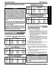
SEAT
WIDTH
*14
16
18
20
SEAT DEPTH
16
REAR
MIDDLE
MIDDLE
MIDDLE
17
REAR
MIDDLE
MIDDLE
MIDDLE
18
REAR
MIDDLE
MIDDLE
MIDDLE
FACTORY SETTINGS - MOTOR MOUNTING POSITIONS
(R2
BASIC
AND R2
JR
)
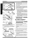
SEAT
WIDTH
*14
16
18
20
SEAT DEPTH
16
N/A
FRONT
FRONT
FRONT
17
N/A
FRONT
FRONT
FRONT
18
N/A
FRONT
FRONT
FRONT
FACTORY SETTINGS - MOTOR MOUNTING POSITIONS
(R2
STANDARD
)
*NOTE: 14 wide is only for R2
JR
.
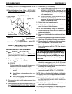
SEAT
WIDTH
*14
16
18
20
SEAT DEPTH
16
N/A
FRONT
FRONT
FRONT
17
N/A
FRONT
FRONT
FRONT
18
N/A
FRONT
FRONT
FRONT
USERS' WEIGHT 251 TO 300 LBS
(FWD MOTORS WITH MOTOR LOCKS ONLY)-
MOTOR MOUNTING POSITIONS
SEAT
WIDTH
*14
16
18
20
SEAT DEPTH
16
N/A
MIDDLE
MIDDLE
MIDDLE
17
N/A
MIDDLE
MIDDLE
MIDDLE
18
N/A
MIDDLE
MIDDLE
MIDDLE
USERS' WEIGHT 201 TO 250 LBS -
MOTOR MOUNTING POSITIONS
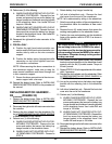
SEAT
WIDTH
*14
16
18
20
SEAT DEPTH
16
REAR
REAR
REAR
REAR
17
REAR
REAR
REAR
REAR
18
REAR
REAR
REAR
REAR
USERS' WEIGHT 200 LBS AND UNDER -
MOTOR MOUNTING POSITIONS
PROCEDURE 13FWD WHEELCHAIRS
F
W
D
W
H
E
E
L
C
H
A
I
R
S