


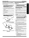
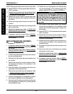


75
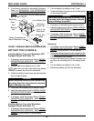
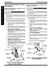
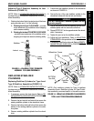
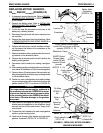
Adjusting Type C Stabilizer Assembly for User
Preference (FIGURE 15)
NOTE: Refer to STABILIZER INDENTIFICATION in
the beginning of this section to determine correct sta-
bilizer assembly.
1. Rotating the locknut that is located on top of the lower
spring provides one (1) of the following:
A. Rotating the locknut CLOCKWISE - provides
more resistance of the stabilizer when stopping
and increases stability.
B. Rotating the locknut COUNTER-CLOCKWISE
- provides less resistance of the stabilizer when
stopping and improves obstacle climbing ability.
FIGURE 15 - ADJUSTING TYPE C STABILIZER
ASSEMBLY FOR USER PREFERENCE
Stabilizer
Locknut
Lower
Spring
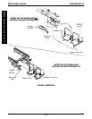
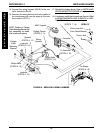
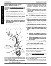
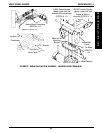
FIGURE 16 - REPLACING STABILIZER CYLINDERS FOR
TYPE A AND TYPE B STABILIZER ASSEMBLIES
Wheelchair Frame
Locknuts
TOP Hex
Bolt
BOTTOM
Hex Bolt
Stabilizer
Plates
Jam Nut
Stabilizer
Cylinder
5. Position the new stabilizer cylinder on the wheelchair
as shown in FIGURE 16.
6. Secure the top of the new stabilizer cylinder to the
wheelchair frame with the hex bolt and locknut.
WARNING
DO NOT overtighten. Stabilizer cylinder will not
operate properly.
7. Secure the bottom of the new stabilizer cylinder to the
stabilizer plates with the hex bolt and locknut.
8. Repeat STEPS 2-7 for the opposite side of the wheel-
chair, if necessary.
9. Tighten the jam nut on the stabilizer cylinder.
10. Adjust the front stabilizer(s). Refer to
ADJUSTING
STABILIZERS in this procedure of the manual.
11. If necessary, install the front shroud. Refer to
REMOV-
ING/INSTALLING SHROUDS in PROCEDURE 10
of this manual.
NOTE: Only stabilizer cylinder for Type A stabilizer
assemlby shown. Stabilizer cylinder for Type B stabi-
lizer assembly removes/installs in the same manner.
REPLACING STABILIZER
CYLINDERS
Replacing Stabilizer Cylinders for Type A and
Type B Stabilizer Assemblies (FIGURE 16)
NOTE: Refer to STABILIZER INDENTIFICATION in
the beginning of this section to determine correct sta-
bilizer assembly.
1. If necessary, remove the front shroud. Refer to RE-
MOVING/INSTALLING SHROUDS in PROCEDURE
10 of this manual.
2. Remove the top hex bolt and locknut that secure the
existing stabilizer cylinder to the wheelchair frame.
3. Remove the bottom bolt and locknut that secure the
bottom of the existing stabilizer cylinder to the stabi-
lizer plates.
4. Remove existing stabilizer cylinder from the wheel-
chair.
MWD WHEELCHAIRS
M
W
D
W
H
E
E
L
C
H
A
I
R
S
PROCEDURE 14