


37
ADJUSTING SEAT WIDTH -
INTEGRATED SLING SEATS
(FIGURE 1)
1. If necessary remove the shrouds. Refer to REMOV-
ING/INSTALLING SHROUDS in PROCEDURE 10
of
this manual.
2. Perform one (1) of the following:
FWD WHEELCHAIRS -
A. Remove the battery boxes from the wheelchair.
INSTALLING/REMOVING BATTERY BOXES in
PROCEDURE 13 of this manual.
B. Fold the battery tray. Refer to
FOLDING BATTERY
TRAY FOR TRANSPORT in PROCEDURE 13
of this manual.
MWD WHEELCHAIRS -
A. Remove the battery boxes from the wheelchair.
INSTALLING/REMOVING BATTERY BOXES
in PROCEDURE 14 of this manual.
B. Remove the battery tray from the wheelchair.
Refer to
INSTALLING/REMOVING BATTERY
TRAY in PROCEDURE 14 of this manual.
3. Remove the existing back and seat upholstery from the
wheelchair. Refer to
REPLACING BACK UPHOL-
STERY in PROCEDURE 5 of this manual and RE-
PLACING SEAT UPHOLSTERY in PROCEDURE 5
of the owner's manual, part number 1080722.
NOTE: If adjusting the seat width of the wheelchair, the back
and seat upholstery MUST be changed as well.
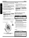
4. Remove the hex bolts and locknuts that secure the two
(2) pivot links to the wheelchair frame and crossbraces.
Refer to the following chart to determine if new pivot links
will be needed:
PIVOT LINK SEAT WIDTH RANGE (in inches)
16-18 or 20
5. Remove the dust covers from the bottom of the cross-
braces.
NOTE: Note position of the tie wraps that secure the wir-
ing harness to the crossbraces.
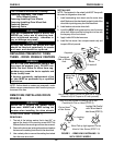
WARNING
After ANY adjustments, repair or service
and BEFORE use, make sure all attaching
hardware is tightened securely - other-
wise injury or damage may result.
This Procedure Includes the Following:
Adjusting Seat Width - Integrated Sling Seats
Replacing Crossbraces - Captain's Seats
PROCEDURE 11CROSSBRACES
C
R
O
S
S
B
R
A
C
E
S
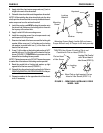
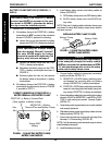
6. Cut the tie wraps that secure the wiring harness to
the crossbrace.
7. Remove the hex bolts, washers and locknuts that se-
cure the bottom of the two (2) crossbraces to the
wheelchair frame.
8. Remove the hex bolt, coved spacers, washers and
locknut that secure the two (2) existing crossbraces
together.
NOTE: Note coved spacer, washer and locknut order for
reinstallation.
9. Remove the four (4) pivot tube plug pins from the bot-
tom of the two (2) existing crossbraces.
10. Install the four (4) pivot tube plug pins into the bottom
of the two (2) new crossbraces.
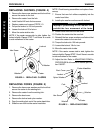
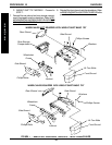
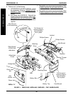
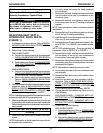
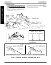
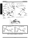
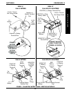
11. Assemble the two (2) new crossbraces together. Re-
fer to DETAIL "A" in FIGURE 1 for hardware orienta-
tion.
NOTE: FWD wheelchairs only - There are right and left
crossbraces. Refer to DETAIL "B" in FIGURE 1.
12. Reinstall the hex bolts, washers and locknuts that se-
cure the bottom of the two (2) new crossbraces to
the wheelchair frame and tighten securely.
13. Reinstall the hex bolts and locknuts that secure the
new/existing pivot links to the wheelchair frame and
crossbraces and tighten.
NOTE: Seat widths are stamped on the pivot links.
14. Secure wiring harness to the new crossbraces with
new tie wraps.
15. Reinstall the black dust covers onto the bottom of the
crossbraces.
16. Install the new back and seat upholstery onto the
wheelchair. Refer to
REPLACING BACK UPHOL-
STERY in PROCEDURE 5 of this manual and RE-
PLACING SEAT UPHOLSTERY in PROCEDURE
5 of the owner's manual, part number 1080722.
17. Change the width of the battery tray. Refer to one (1)
of the following:
FWD WHEELCHAIRS -
CHANGING WIDTH OF
BATTERY TRAY in PROCEDURE 13 of this manual.
MWD WHEELCHAIRS -
CHANGING WIDTH OF
BATTERY TRAY in PROCEDURE 14 of this manual.
18. Perform one (1) of the following:
FWD WHEELCHAIRS -
A. Unfold the battery tray. Refer to
FOLDING BAT-
TERY TRAY FOR USE in PROCEDURE 13 of
this manual.
B. Reinstall the battery boxes onto the wheelchair.
INSTALLING/REMOVING BATTERY BOXES in
PROCEDURE 13 of this manual.