


72
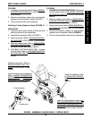
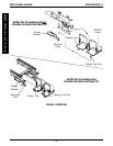
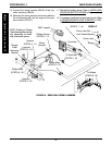
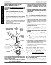
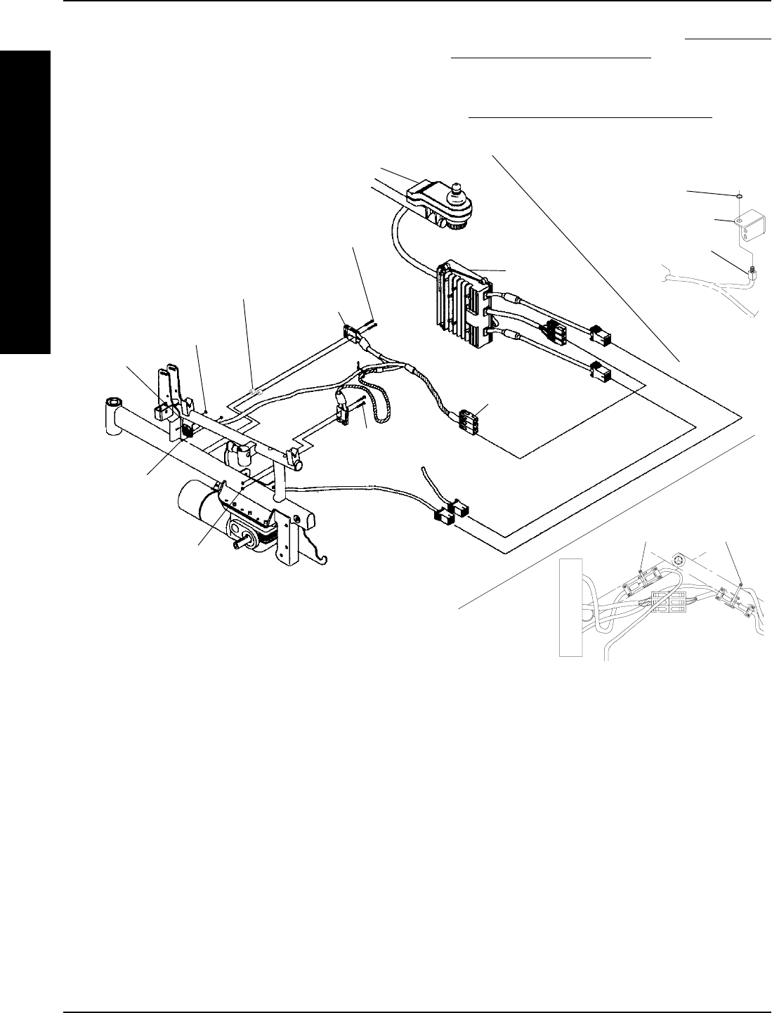
FIGURE 10 - REPLACING WIRING HARNESS
Charger
Cable
Mounting
Bracket
Wiring
Harness
To Controller
(STEPS 3, 15)
MKIV Joystick
Controller
Phillips Screws
(STEPS 4, 11)
Phillips Bolts
(STEPS 6, 13)
Locknuts
(STEPS 6, 13)
Spacers
(STEPS 4, 11)
Locknuts
(STEPS 5, 12)
DETAIL "A"
Phillips Bolts
(STEPS 5, 12)
(STEPS 7, 14)
Phono Jack Nut
Phono Jack
Limit Switch Bracket
NOTE: Position of Charger
Cable Mounting Bracket may
vary depending on wheel-
chair model and options.
Tie Wraps
(STEPS 8, 16)
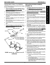
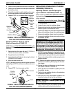
15. Connect the wiring harness (BLUE) to the con-
troller connector (BLUE).
16. Resecure the wiring harness and motor cables to
the crossbraces with new tie wraps at the posi-
tions noted in STEP 8.
17. Reinstall the battery boxes. Refer to
INSTALLING/
REMOVING BATTERY BOXES in this procedure of
manual.
18. If necessary, install the front and rear shrouds. Refer
to
REMOVING/INSTALLING SHROUDS in PRO-
CEDURE 10 of this manual.
PROCEDURE 14 MWD WHEELCHAIRS
M
W
D
W
H
E
E
L
C
H
A
I
R
S