


42
PROCEDURE 12 BATTERIES
B
A
T
T
E
R
I
E
S
CONNECTING BATTERY CABLES
WARNING
NEVER allow any of your tools and/or battery
cable(s) to contact BOTH battery terminal(s)/post(s)
at the same time. An electrical short may occur
and serious personal injury or damage may occur.
The use of rubber gloves and safety glasses is rec-
ommended when working with batteries.
Dual U1 or Dual Group 22 Battery Boxes
Perform one (1) of the following methods for connecting
the battery cable(s):
A. FOR DUAL U1 BATTERIES - Use direct mount
method. Refer to FIGURES 2, and 3.
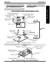
B. FOR DUAL GROUP 22 NF BATTERIES THAT
HAVE MOUNTING HOLES IN THE BATTERY
TERMINAL(S)/POST(S) - Use direct mount
method. Refer to FIGURES 2, 3 AND 4.
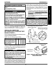
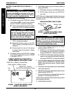
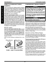
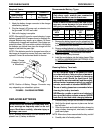
C. FOR DUAL GROUP 22 NF BATTERIES THAT
DO NOT HAVE MOUNTING HOLES IN THE
BATTERY TERMINAL(S)/POST(S) - Use battery
clamp method. Refer to FIGURES 4, 5 AND 6.
DIRECT MOUNT METHOD (FIGURE 2 AND 3).
1. Install battery terminal cap(s) onto battery cable(s) as
follows (FIGURE 2):
DUAL U1 BATTERIES:
A. ORANGE battery terminal cap onto RED bat-
tery cable.
B. GRAY battery terminal cap onto BLACK battery
cable.
DUAL GROUP 22 NF BATTERIES:
A. RED battery terminal cap onto RED battery cable.
B. BLACK battery terminal cap onto BLACK bat-
tery cable.
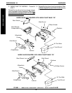
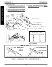
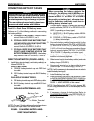
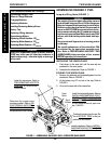
FIGURE 2 - CONNECTING BATTERY CABLES -
DIRECT MOUNT METHOD
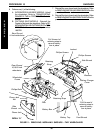
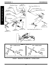
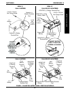
CAUTION
When connecting the battery cables to the
battery(ies), the battery cable(s) MUST be con-
nected to the battery terminal(s)/post(s) as
shown in DETAIL “A” or DETAIL “B” of FIGURE 3
(depending on battery type), otherwise dam-
age to the battery cable may result when in-
stalling battery terminal caps.
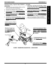
2. Connect battery cable(s) to battery(ies) terminal(s)/
post(s) as follows (DETAIL “A” or DETAIL “B”of FIG-
URE 3, depending on battery type):
A. NEGATIVE (-) BLACK battery cable to NEGA-
TIVE (-) battery terminal/post.
B. POSITIVE (+) RED battery cable to POSITIVE
(+) battery terminal/post.
3. Secure the battery cable(s)/ring terminal(s) to the
battery terminal(s)/post(s), BLACK to NEGATIVE
(-) and RED to POSITIVE (+), with the provided
1/4-20 x 7/8-inch hex flange screw and hex flange
locknut. Securely tighten. (DETAIL “A” or DETAIL
“B”of FIGURE 3, depending on battery type).
4. Verify all battery cable(s)/ring terminal(s) are correctly
installed and securely tightened.
5. Slide terminal cap(s) down battery cable(s) and onto
battery clamps (FIGURE 3).
6. Secure each terminal cap in place with a tie-wrap
(Use tie-wraps 11-1/2-inches long) (FIGURE 3).
NOTE: It will be necessary to trim excess tie-wrap in order to
install the battery box top(s).
7. Install the battery box top(s).
8. Install the battery box(es) into the wheelchair. Refer
to
INSTALLING/REMOVING BATTERY BOX(ES) in
the PROCEDURE 13 - FWD MODELS or PROCE-
DURE 14 - MWD MODELS of this manual.
NOTE: New Battery(ies) MUST be fully charged BE-
FORE using, otherwise the life of the battery(ies) will be
reduced.
9. If necessary, charge the battery(ies). Refer to
CHARGING BATTERIES in the PROCEDURE 13 -
FWD MODELS or PROCEDURE 14 - MWD MOD-
ELS of this manual.
Battery Cable
Battery Terminal
Cap
NOTE: Only one (1) battery cable and terminal cap shown
for clarity. Both caps install in the same manner.
INSTALLING BATTERY TERMINAL CAPS