


61
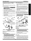
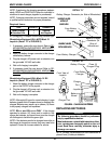
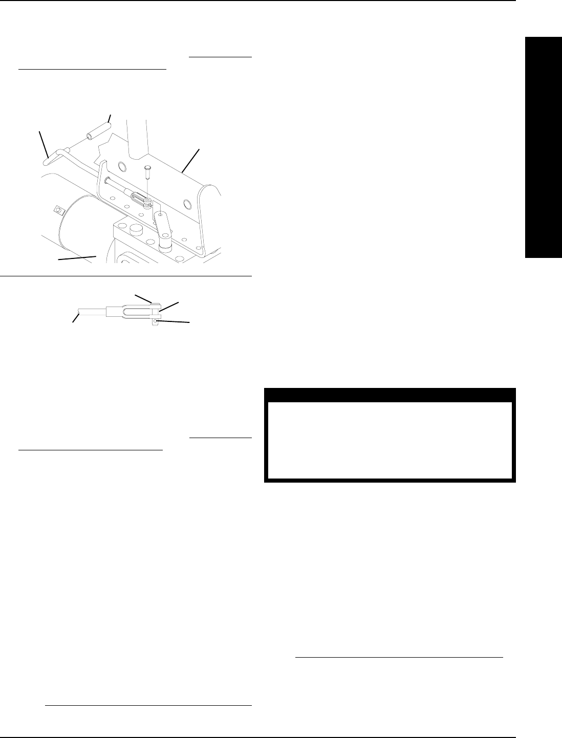
FIGURE 21 - REPLACING CLUTCH HANDLES -
RANGER II FWD BASIC
Tip
(STEPS 2, 6, 8)
Outside of
Wheelchair
Motor/
Gearbox
Clutch Handle
(STEPS 4, 7)
Clutch Handle
(STEP 9)
Pin
(STEPS 3, 10)
Detent Ball
Motor/Gearbox
DETAIL "A"
5. Perform one (1) of the following:
A. WHEELCHAIR EQUIPPED WITH FLIP-UP RE-
MOVABLE FOOTBOARD - Remove the hex
screws and spacers that secure the battery tray
hanger bracket and footboard mounting bracket
to the wheelchair frame.
B. WHEELCHAIR NOT EQUIPPED WITH FLIP-UP
REMOVABLE FOOTBOARD - Remove the front
hex screw that secures the battery tray hanger
bracket to the wheelchair frame.
5. Rotate battery tray hanger bracket up.
6. Left side of wheelchair only - Remove the front dust
cover from the end of the crossbrace.
NOTE: Left is determined by sitting in the wheelchair.
7. Remove the pin that secures the clutch handle to the
existing motor/gearbox.
8. Disconnect clutch handle from existing motor/gear-
box.
9. Note mounting position of motor/gearbox on the wheel-
chair frame for installation of the new motor/gearbox.
10. Remove the six (6) socket screws that secure the ex-
isting motor/gearbox to the wheelchair frame.
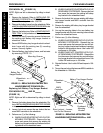
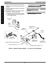
11. Position the new motor/gearbox on the wheelchair
frame at the position noted in STEP 9 as shown in
FIGURE 22.
CAUTION
The longer socket screws must be positioned in
the mounting holes on the OUTSIDE of the wheel-
chair frame and the short socket screws must be
in the mounting holes on the INSIDE of the wheel-
chair frame. Otherwise damage to the gearbox
may result.
12. Use Loctite 242 and tighten the motor/gearbox to the
wheelchair frame securely with the six (6) socket
screws. Torque to 60-inch pounds.
13. Connect the clutch handle to the new motor/gearbox
and line up the mounting holes.
14. Insert the pin through clutch handle and new motor/
gearbox as shown in DETAIL "B" in FIGURE 22.
NOTE: Make sure the detent ball on the pin is fully visible.
15. Repeat STEPS 6-13 for the opposite side of the wheel-
chair, if necessary.
16. Reinstall the drive wheels onto the wheelchair. Refer
to
REMOVING/INSTALLING DRIVE WHEELS in
PROCEDURE 9 of this manual.
17. Left side of wheelchair only - Reinstall the front dust
cover onto the end of the crossbrace.
18. Line up the mounting hole in the battery tray hanger
bracket with the mounting hole in the wheelchair frame.
11. Repeat STEPS 2-10 for the opposite side of the
wheelchair, if necessary.
12. Reinstall the battery boxes. Refer to
INSTALLING/
REMOVING BATTERY BOXES in this procedure
of the manual.
REPLACING MOTOR/GEARBOX -
R2
BASIC
AND R2
JR
(FIGURE 22)
1. Remove the battery boxes. Refer to INSTALLING/
REMOVING BATTERY BOXES in this procedure of
the manual.
2. Perform one (1) of the following:
A. For R2
BASIC
- Proceed to STEP 3
B. FOR R2
JR
Cut the tie wrap that secures the following con-
nections to the wire connector support:
l The right hand motor and controller con-
nection.
l The left hand motor and controller con-
nection.
l Battery wiring harness (BLUE)and control-
ler connector (BLUE).
3. Disconnect the right and left motor connector from
the controller.
4. Remove the drive wheels from the wheelchair. Re-
fer to
REMOVING/INSTALLING DRIVE WHEELS
in PROCEDURE 9 of this manual.
PROCEDURE 13FWD WHEELCHAIRS
F
W
D
W
H
E
E
L
C
H
A
I
R
S