


55
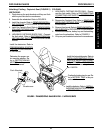
FOR MODEL R2
JR
(FIGURE 17).
NOTE: Right and left is determined by sitting in wheel-
chair.
1. Remove the footrests. Refer to INSTALLING /RE-
MOVING FOOTRESTS in PROCEDURE 3 of the
Owner's Manual, part number 1080722.
2. Remove the front and rear shrouds. Refer to RE-
MOVING/INSTALLING SHROUDS in PROCE-
DURE 10 in this manual.
3. Remove the battery boxes from the wheelchair. Re-
fer to
INSTALLING/REMOVING BATTERY BOXES
in this procedure of the manual.
4. Fold battery tray. Refer to
FOLDING/UNFOLD-
ING BATTERY TRAY in this procedure of the
manual.
5. Loosen, but do not remove the rear locknut that se-
cures MKIV controller to the wheelchair.
6. Remove the front hex screw that secures the ex-
isting left battery tray bracket to the wheelchair
frame.
7. Remove the locknut that secures existing left battery
tray hanger bracket and MKIV controller from the
wheelchair.
8. Remove the existing left battery tray hanger bracket
from the wheelchair.
9. Line up the mounting holes in the new battery tray
hanger bracket with the front mounting hole and rear
stud on the wheelchair frame.
10. Reinstall the front hex screw that secures the new
left battery tray hanger bracket to the wheelchair
frame. Use Loctite 242 and torque to 156-in/lbs.
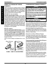
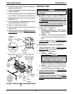
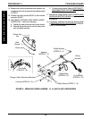
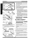
FIGURE 17 - REPLACING LEFT BATTERY TRAY
HANGER BRACKET FOR MODEL R2
JR
MKIV
Controller
Rear Locknut - Loosen,
but Do Not Remove
Locknut
Battery Tray
Hanger Bracket
Front Hex
Screw
Wheelchair
Frame
11. Reinstall locknut that secures the front of the MKIV
controller and rear of the left battery tray hanger
bracket to the wheelchair frame. Use Loctite 242
and torque to 156-in/lbs.
12. Tighten the rear locknut that secures MKIV controller
to the wheelchair and torque to 156-in/lbs.
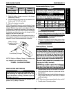
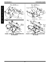
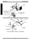
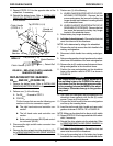
REPLACING WIRING HARNESS
(FIGURE 18)
16, 18, and 20-inch Wide Models
1. If necessary, remove the front and rear shrouds. Re-
fer to
REMOVING/INSTALLING SHROUDS in PRO-
CEDURE 10 of this manual.
2. Remove the battery boxes. Refer to
INSTALLING/
REMOVING BATTERY BOXES in this procedure
of the manual.
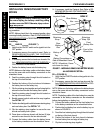
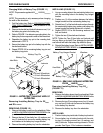
3. HIGH BACK CAPTAIN'S SEAT MODEL WHEEL-
CHAIRS ONLY (DETAIL "A") - Perform the following:
A. Disconnect the limit switch. Refer to
DISCON-
NECTING/CONNECTING LIMIT SWITCH in
PROCEDURE 8 of this manual.
B. Remove the phono jack nut that secures the
phono jack to the side shroud.
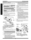
4. Disconnect the wiring harness (BLUE) from the con-
troller connector (BLUE).
5. Remove the two (2) phillips screws and spacers that
secure the rear battery connector to the wheelchair
frame.
6. Remove the two (2) phillips bolts and locknuts that
secure the front battery connector to wheelchair frame.
7. Remove the two (2) phillips screws that secure the
wiring harness to the charger cable mounting bracket.
8. Note the position of the tie wraps that secure the ex-
isting wiring harness and motor cables to the
crossbraces.
9. Cut the tie wraps that secure the existing wiring har-
ness and motor cables to the crossbraces.
10. Remove the existing wiring harness from wheelchair.
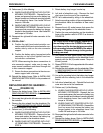
11. Position the rear battery connector of the new wiring
harness on the wheelchair frame as shown in FIG-
URE 18 and secure with the two (2) phillips screws
and spacers.
12. Position the front battery connector on the wheelchair
frame as shown in FIGURE 18 and secure with the
two (2) phillips bolts and locknuts.
13. Secure the wiring harness to existing charger cable
mounting bracket on the seat frame with the two (2)
phillips screws.
PROCEDURE 13FWD WHEELCHAIRS
F
W
D
W
H
E
E
L
C
H
A
I
R
S