


73
STABILIZERS
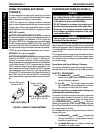
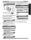
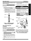
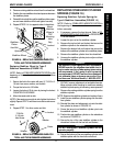
FIGURE 12 - ADJUSTING STABILIZERS - SPRINGS
Measure This Height
Stabilizer
NOTE: If the user's approximate weight is not listed above,
use the HIGHEST listed approximate weight closest to user's
weight as a starting point to adjust the stabilizer spring.
Adjustment Nut
Spring
HEIGHT
MEASURED
(APPROXIMATE
- IN INCHES)
4-3/16
4
3-7/8
3-11/16
3-1/2
USER'S WEIGHT
(APPROXIMATE
- IN POUNDS)
100
150
200
250
300
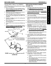
ADJUSTING SPRINGS FOR TYPE A
STABILIZER ASSEMBLY (FIGURE 12)
NOTE: Refer to STABILIZER INDENTIFICATION
above to determine correct stabilizer assembly.
WARNING
Injury or damage can occur if the height of the
stabilizer springs does not correspond to the ap-
proximate weight of the user. If the height of the
stabilizer springs does not correspond to the ap-
proximate weight of the user, the wheelchair will
feel less stable and possibly cause the footrests/
legrests to drag the ground.
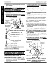
If adjusting a new cylinder spring, it MUST be com-
pressed to the 3-1/2-inch height (FIGURE 12) BEFORE
adjusting the stabilizer spring to correspond to the
approximate weight of the user. Otherwise the sta-
bilizer will not work properly.
NOTE: If the height of the stabilizer springs is less than the
height that corresponds to the approximate weight of the
user, the wheelchair will not be able to clear 2-inch obstacles.
NOTE: The stabilizer springs are factory set for a user weigh-
ing approximately 300-pounds. Use
FIGURE 12
as a start-
ing point when adjusting the stabilizer spring.
NOTE: The following adjustment should be made with an
unoccupied wheelchair.
1. Determine the approximate weight of the user.
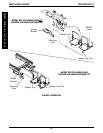
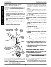
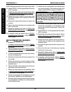
STABILIZER IDENTIFICATION (FIGURE 11)
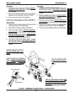
NOTE: Depending on the date of manufacture, the wheelchair will have one (1) of the following types of
stabilizer assemblies. Refer to the chart below to determine the correct stabilizer assembly.
TYPE A TYPE B TYPE C
Wheelchairs built Whelchairs built Whelchairs built
before 7/1/1999 between 7/1/1999 and 3/1/2000 after 3/1/2000
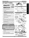
2. NEW STABILIZER SPRINGS ONLY - Rotate adjust-
ment nut DOWN until the 3-1/2-inch height is obtained.
3. Refer to FIGURE 12 to determine the height of the
stabilizer spring.
4. Rotate the adjustment nut UP or DOWN to adjust the
stabilizer spring to the height determined in STEP 2.
5. Adjust the for user preference. Refer to ADJUSTING
TYPE A STABILIZER ASSEMBLY FOR USER PREF-
ERENCE in this procedure of the manual.
FIGURE 11 -STABILIZER IDENTIFICATION
MWD WHEELCHAIRS
M
W
D
W
H
E
E
L
C
H
A
I
R
S
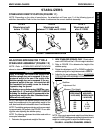
PROCEDURE 14