


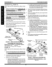

62
19. Perform one (1) of the following:
A. WHEELCHAIR EQUIPPED WITH FLIP-UP RE-
MOVABLE FOOTBOARD - Reinstall the hex
screws and spacers that secure the battery tray
hanger bracket and footboard mounting bracket
to the wheelchair frame. Use Loctite 242 and
torque to 156-in/lbs.
B. WHEELCHAIR NOT EQUIPPED WITH FLIP-UP
REMOVABLE FOOTBOARD - Reinstall the front
hex screw that secures the battery tray hanger
bracket to the wheelchair frame. Use Loctite 242
and torque to 156-in/lbs.
20. Reconnect the right and left motor connector to the
controller.
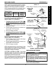
21. FOR R2
JR
ONLY -
A. Position the right hand motor/controller con-
nection and the left hand motor/controller con-
nection side by side on the wire connector
support.
B. Position the battery wiring harness/controller
connection on top of the right/left hand mo-
tor/controller connections.
NOTE: When securing the above connections to
wire connector support, make sure to wrap tie-
wrap around crossbrace and thread through slot
in wire connector support.
C. Secure the above connections to the wire con-
nector support with a tie-wrap.
22. Reinstall the battery boxes. Refer to INSTALLING/
REMOVING BATTERY BOXES in this procedure of
the manual.
REPLACING MOTOR/GEARBOX -
R2
STANDARD
(FIGURE 23)
1. Remove the battery boxes. Refer to INSTALLING/
REMOVING BATTERY BOXES in this procedure of
the manual.
2. Disconnect the right and/or left motor connector from
the controller.
3. Remove the drive wheels from the wheelchair. Re-
fer to
REMOVING/INSTALLING DRIVE WHEELS
in PROCEDURE 9 of this manual.
4. Perform one (1) of the following:
A. WHEELCHAIR EQUIPPED WITH FLIP-UP RE-
MOVABLE FOOTBOARD - Remove the hex
screw and washer that secure the battery tray
hanger bracket to the wheelchair frame.
B. WHEELCHAIR NOT EQUIPPED WITH FLIP-
UP REMOVABLE FOOTBOARD - Proceed to
STEP 6.
PROCEDURE 13 FWD WHEELCHAIRS
F
W
D
W
H
E
E
L
C
H
A
I
R
S
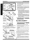
5. Rotate battery tray hanger bracket up.
6. Left side of wheelchair only - Remove the front
dust cover from the end of the crossbrace.
NOTE: left is determined by sitting in the wheelchair.
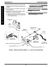
7. Note the mounting position of the motor/gearbox on
the wheelchair frame for installation of new motor/
gearbox.
8. Remove the six (6) socket screws that secure the
existing motor/gearbox to the wheelchair frame.
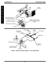
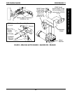
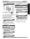
9. Position the new motor/gearbox on the wheelchair
frame at the position noted in STEP 6 as shown in
FIGURE 23.
CAUTION
The longer socket screws must be positioned in
the mounting holes on the OUTSIDE of the wheel-
chair frame and the short socket screws must be
in the mounting holes on the INSIDE of the wheel-
chair frame. Otherwise damage to the gearbox
casting can result.
10. Use Loctite 242 and tighten battery tray mounting
bracket and motor/gearbox to the wheelchair frame
securely with the six (6) socket screws. Torque to
60-inch pounds.
11. Repeat STEPS 2-10 for the opposite side of the wheel-
chair, if necessary.
12. Reinstall the drive wheels onto the wheelchair. Refer
to
REMOVING/INSTALLING DRIVE WHEELS in
PROCEDURE 9 of this manual.
13. Line up the mounting hole in the battery tray hanger
bracket with the mounting hole in the wheelchair
frame.
14. Left side of wheelchair only - Reinstall the front dust
cover onto the end of the crossbrace.
15. Perform one (1) of the following:
A. WHEELCHAIR EQUIPPED WITH FLIP-UP RE-
MOVABLE FOOTBOARD - Reinstall the hex
screws and spacers that secure the battery tray
hanger bracket and footboard mounting bracket
to the wheelchair frame. Use Loctite 242 and
torque to 156-in/lbs.
B. WHEELCHAIR NOT EQUIPPED WITH FLIP-
UP REMOVABLE FOOTBOARD - Reinstall the
front hex screw that secures the battery tray
hanger bracket to the wheelchair frame. Use
Loctite 242 and torque to 156-in/lbs.
16. Reconnect the right and/or left motor connector to the
controller.
17. Reinstall the battery boxes. Refer to
INSTALLING/
REMOVING BATTERY BOXES in this procedure of
the manual.