


16
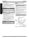
Footplate
Clamps
Removable
Footboard
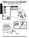
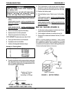
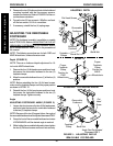
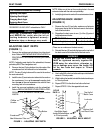
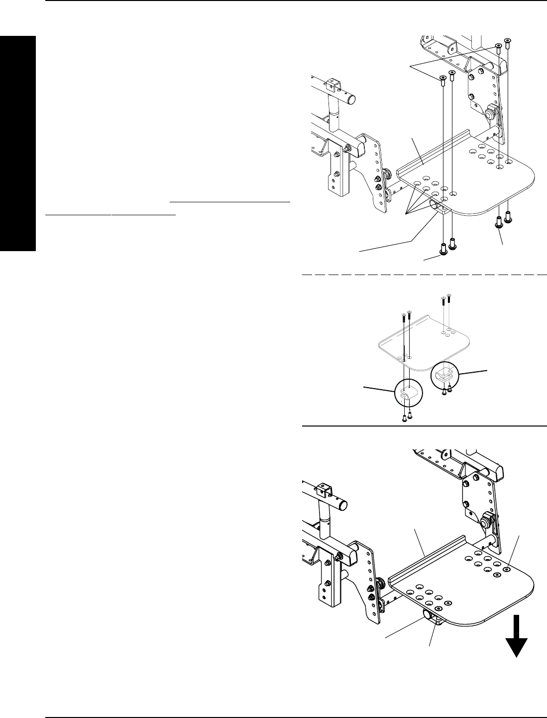
ADJUSTING DEPTH
Mounting
Positions
Flat Head Screws
Barrel Nut
Barrel Nut
DETAIL "A"
Proper
Footplate
Clamp
Position for
MWD
Wheelchairs
Proper
Footplate
Clamp
Position for
FWD
Wheelchairs
ADJUSTING THE REMOVABLE
FOOTBOARD
NOTE:This footboard assembly is available on models
built AFTER 3/1/00. Refer to ADJUSTING THE FLIP-UP
REMOVABLE FOOTBOARD for the footboard assem-
bly on models built BEFORE 3/1/00 in this procedure of
the manual.
NOTE: The following procedures are for both FWD and
MWD fwheelchairs, unless otherwise noted.
Depth (FIGURE 3)
NOTE: There is no footboard depth adjustment for 16-
inch wide MWD wheelchairs.
1. Remove the four (4) flat head screws and barrel nuts
that secure the removable footboard to the two (2)
footplate clamps.
2. Move the removable footboard to one (1) of the four (4)
positions.
NOTE: Before reinstalling the four (4) flat head screws,
make sure the footplate clamps are in the proper position
as shown in DETAIL "A".
3. Reinstall the four (4) flat head screws and barrel nuts
that secure the removable footboard to the two (2)
footplate clamps. Tighten securely.
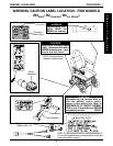
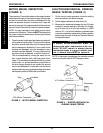
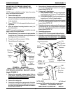
Angle
ADJUSTING FOOTBOARD ANGLE (FIGURE 3).
1. Loosen, but do not remove, the four (4) flat head screws
and barrel nuts that secure the removable footboard
to the two (2) footplate clamps.
NOTE: Because of the two (2) support tubes, the angle of
the removable footboard can be adjusted downward ONLY.
2. Grasp the front of the removable footboard and rotate
it DOWNWARD until the desired angle is reached.
3. While holding the removable footboard in place, tighten
the four (4) flat head screws and barrel nuts securely.
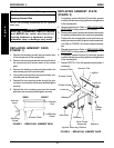
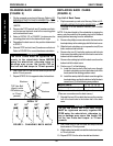
FIGURE 3 - ADJUSTING FLIP-UP
REMOVABLE FOOTBOARD
Removable
Footboard
Barrel Nut
Flat
Head
Screw
Angle Can Be Adjusted
Downward ONLY
FRONT
Footplate
Clamp
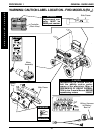
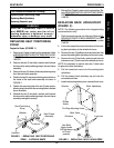
ADJUSTING FOOTBOARD ANGLE
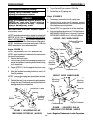
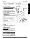
5. Resecure the two (2) footboard pivots to the footboard
mounting brackets with the hex screws, spacers,
washers and locknuts. Refer to FIGURE 2 for the cor-
rect hardware orientation.
6. Torque the two (2) hex screws to 156in/lbs. and back
off the hex screws 1/8-1/4 of a revolution.
7. If necessary, reinstall the four (4) caplug caps.
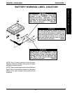
PROCEDURE 3
F
R
O
N
T
R
I
G
G
I
N
G
S
FRONT RIGGINGS