


76
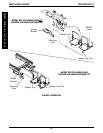
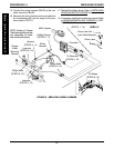
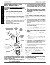
Replacing Stabilizer Cylinders for Type C
Stabilizer Assemblies (FIGURE 17)
NOTE: Refer to STABILIZER INDENTIFICATION in the
beginning of this section to determine correct stabilizer
assembly.
1. Place a 1/2-inch block underneath drive wheel.
2. Remove the top mounting screw and locknut that se-
cures the top of the stabilizer cylinder to the wheel-
chair frame.
2. Note the mounting position of the existing stabilizer
cylinder for proper installation of the new stabilizer cyl-
inder.
3. Remove the bottom mounting screw, washers and
locknut that secures the bottom of the stabilizer cylin-
der to the swing arm.
4. Remove the existing stabilizer cylinder.
NOTE: Stabilizer assembly exploded away for clarity.
It is not necessary to remove the stabilizer assembly
from the wheelchair frame.
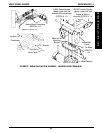
FIGURE 17 - REPLACING STABILIZER CYLINDERS FOR
TYPE C STABILIZER ASSEMBLIES
Bottom
Mounting
Screw
Locknuts
Bottom of
Stabilizer
Cyliner
Top
Mounting
Screw
Locknut
zRight Hand side of
Wheelchair Frame
Washer
Swing
Arm
Top of
Stabilizer
Cylinder
There is no
need to remove
this mounting screw
and locknut
PROCEDURE 14 MWD WHEELCHAIRS
M
W
D
W
H
E
E
L
C
H
A
I
R
S
5. Secure the bottom of the NEW stabilizer cylinder to the
mounting hole on the swing arm noted in STEP 2 with
the mounting screw, washers, and locknut. Loosely
tighten.
6. Secure the top of the stabilizer cylinder to the wheel-
chair frame with the top mounting screw and locknut.
Loosely tighten.
7. Torque both mounting screws to 13 ft/lbs and then back
off 1/8 to 1/4 turn.
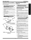
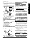
NOTE: The length of the new stabilizer cylinder must be
adjusted to match the length of the stabilizer cylinder just
removed.
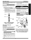
8. Measure the distance between the top mounting hole
and the bottom mounting hole on the existing stabilizer
cylinder. Note this distance as distance “A” . Refer to
DETAIL “A”
9. Place the wheelchair on a flat surface so that the stabi-
lizer wheels can hang freely.
10. Loosen the jam nut, located underneath the hex nut
adjuster, by turning CLOCKWISE as viewed from the
top.
11. Rotate the hex nut adjuster in one (1) of the following
directions:
A. Rotating the hex nut adjuster CLOCKWISE, as
viewed from the top, will move the stabilizer wheel
up.
B. Rotating the hex nut adjuster COUNTER - CLOCK-
WISE, as viewed from the top, will move the stabi-
lizer wheel down.
12. When distance “A” is achieved, noted from STEP 8,
retighten the jam nut by rotating COUNTER-CLOCK-
WISE to lock the hex nut adjuster in position.
13. Place the wheelchair on a flat surface with all six wheels
in contact with the surface.
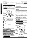
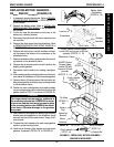
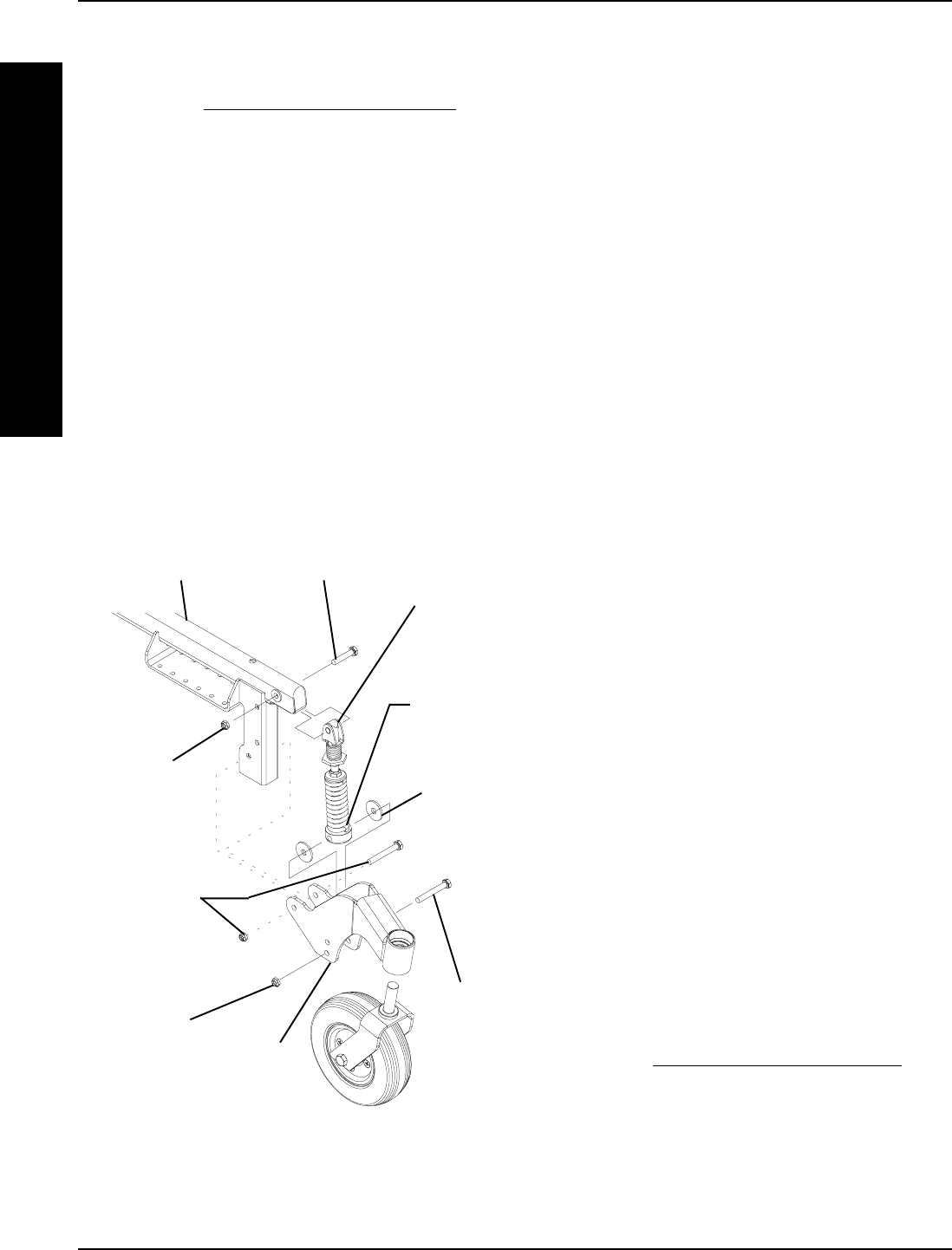
REPLACING STABILIZER WHEEL
Replacing Stabilizer Wheel for Type A and Type
B Stabilizer Assemblies (FIGURE 18)
NOTE: Refer to STABILIZER INDENTIFICATION in the
beginning of this section to determine correct stabilizer as-
sembly.
NOTE: Note the position of the stabilizer wheel for installa-
tion of the new stabilizer wheel.
1. Remove the hex bolt and locknut that secure the exist-
ing stabilizer wheel and spacers to the stabilizer plates.