


SECTION 10—WHEEL LOCKS
9000 Jymni™Pediatric Series 54 Part No 1100868
Adjusting Patient-Operated Wheel Locks
NOTE: For this procedure, refer to FIGURE 10.2.
NOTE: If wheels are pneumatic, before adjusting or replacing the wheel lock assemblies, ensure
that the tires are inflated to the recommended psi on the side wall of tire. The recommended tire
pressure is located on the side wall of the tire.
1. Disengage the wheel locks.
2. Loosen the bolt and locknut that secure the wheel lock to the wheelchair frame.
3. Reposition the wheel lock so that when engaged, the wheel lock shoe embeds the tire
1/8-inch (3/16-inch for pneumatic tires) and holds the occupied wheelchair in place
when pushed.
4. Securely tighten the bolt and locknut or socket screws securing the wheel lock to the
wheelchair frame.
5. Engage the wheel lock.
6. Measure the distance the wheel lock is embedded into the tire (FIGURE 10.2).
NOTE: Any wheel lock adjustment should embed the wheel lock shoe at least 1/8-inch (3/16-inch
if pneumatic tire) into the tire when engaged.
7. Repeat STEPS 1-6 until the wheel lock shoe embeds the tire 1/8-inch (3/16-inch for
pneumatic tires) and holds the occupied wheelchair in place when pushed.
8. Repeat STEPS 1-7 for the opposite wheel lock.
9. Engage both wheel locks and ensure the occupied wheelchair is held in place when
pushed.
ƽ WARNING
If wheel locks do not hold the occupied wheelchair in place, contact a qualified tech-
nician. Otherwise injury or damage may occur.
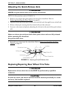
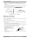
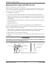
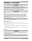
FIGURE 10.2 Adjusting Patient-Operated Wheel Locks
1/8-inch (3/16-inch
pneumatic tires)
Wheel Lock
Shoe
Tire
Wheel Lock
Mounting Positions
Wheel Lock
Handle
Rear Wheel
Wheel Lock Shoe
Bolt and Locknut