


Instruction Manual
IB-106-5081, Rev. 1.0
May 2005
Rosemount Analytical Inc. A Division of Emerson Process Management Index 9-1
Model 5081FG
SECTION 9
INDEX
This index is an alphabetized listing of parts, terms, and procedures having to do with the Haz-
ardous Area Oxygen/Combustibles Transmitter. Every item listed in this index refers to a location
in the manual by one or more page numbers.
A
Absolute Temperature, 1-3
ACCEPT HIGH O
2
Screen, 3-14
ACCEPT LOW O
2
Screen, 3-14
Accuracy, 1-7
Adapter Plate, 2-3
Ambient Temperature Limits, Electronics, 1-8
AMS, 1-4, 1-5
Arithmetic Constant, 1-3
C
CAL key, 3-5
CALCHECK Menu, 3-4, 3-13
Calibration Check Gas, 1-7, 2-11, 3-2
Calibration Check Gas Flow Rate, 3-2
CELL IMPEDANCE Screen, 3-12
CELL T HI Screen, 3-7
Cell Constant, 1-3
Cell Impedance Too High Fault, 6-6
Check Valve, 1-6
Component Checklist, 1-1
CONSTANT Screen, 3-15
D
DIAG Key, 3-5
Diagnostics Menu, 3-4, 3-11
Display Board, 2-9
Display Board Positioning, 2-9
Display Board Replacement, 5-1
DISPLAY Code, 3-6
Drip Loop, 2-6
E
Earth Ground, 2-10
Electrical Installation, 2-9
Electromagnetic Interference (EMI), 2-10
ENTER Key, 3-5
EXIT Key, 3-5
F
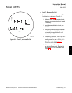
Fault Indications, 6-2
FAULT VAL Screen, 3-7
Faulted Operation Display, 3-1
FSK, 4-1
G
Grounding, 2-10
H
HART Communicator, 4-1
HART Model 275/375 Communicator, 1-4
HART
®
Communicator, 1-1
Hazardous Area Certification, 1-7
Hazardous Area Certification, IRC, 1-8
Hazardous Area Certification, Probe, 1-8
High Probe Temperature Fault, 6-5
I
IN MANUAL? Screen, 3-14
Infrared Remote Control (IRC), 1-1, 1-4
Inner Probe, 1-7
Inputs, 1-8
Inspect, 2-1
Instrument Air, 1-6, 2-11
Insulation, 2-6
Intrinsic Safe, 1-5
Intrinsic Safety (IS), 1-4
IP65, 1-6, 1-8
IRC, 3-5
IRC Power Requirements, 1-8
L
Lengths, 1-3, 1-7
Liquid Crystal Display (LCD), 3-3
Load Requirements, 1-8
Load Resistance, 4-2
9