


Instruction Manual
IB-106-5081, Rev. 1.0
May 2005
Rosemount Analytical Inc. A Division of Emerson Process Management Installation 2-7
Model 5081FG
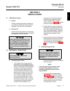
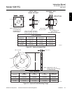
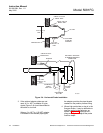
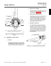
d. Installing Model 5081 Transmitter
1. Ensure all components are available to
install the Model 5081 Transmitter.
2. Choose a method or location to mount
the transmitter.
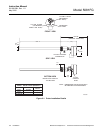
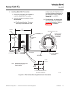
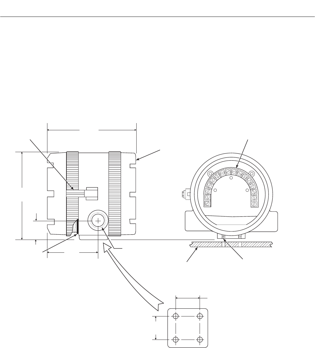
(a) Flat Surface Mounting. The trans-
mitter may be mounted on a flat
surface using the threaded mount-
ing holes located on the bottom of
the transmitter housing. Refer to
Figure 2-6 for installation
references.
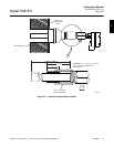
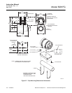
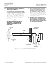
(b) Pipe Mounting. An optional pipe
mounting bracket is available for
this type of installation. Refer to
Figure 2-7 for installation
references.
FLAT SURFACE MOUNTING
PAD HOLE PATTERN
TERMINAL BLOCK (TB)
26020003
TERMINAL END
CAP OMITTED
FOR CLARITY
(THIS VIEW)
1/4-20 THREADS
(4 PLACES)
SURFACE
BY OTHERS
NOTE: DIMENSIONS ARE IN INCHES
WITH MILLIMETERS IN
PARENTHESES.
0.839
(21.31)
0.839
(21.31)
6.35
(161.3)
CIRCUIT
END
6.32
(160.5)
1.32
(33.5)
3.68
(93.5)
TERMINAL
END
O-RING
(2 PLACES)
3/4-14 NPT
(2 PLACES)
THREADED CAP
(2 PLACES)
COVER
LOCK
Figure 2-6. Flat Surface Mounting Dimensional Information
2