


Instruction Manual
IB-106-5081, Rev. 1.0
May 2005
4-2 HART/AMS Rosemount Analytical Inc. A Division of Emerson Process Management
Model 5081FG
LOOP CONNECTORS
USE INTERFACE
00275 0013 ONLY
SERIAL PORT & BATTERY
CHARGER MUST
NOT BE USED IN
HAZARDOUS AREAS
SERIAL PORT
MODEL 5081 TRANSMITTER
TERMINAL BLOCK
LOOP CONNECTORS
4-20 mA SIGNAL LINE
HART
COMMUNICATOR
RL 250≥Ω
ANALOG OUTPUT DEVICE
LEAD SET
HART COMMUNICATOR
REAR PANEL
12
3
5
6
7
8
9
11
12
13
14
15
16
10
4
+
4-20 mA
37420006
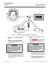
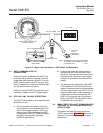
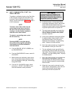
Figure 4-1. Signal Line Connections, > 250 Ohms Lead Resistance
a. Method 1, For Load Resistance ≥ 250
Ohms
Refer to Figure 4-1 and the following in-
struction to connect the HART Communi-
cator to a signal line with 250 ohms or more
of load resistance.
Explosions can result in death or seri-
ous injury. Do not make connections
to the HART Communicator's serial
port, 4-20 mV signal line, or NiCad re-
charger jack in an explosive
atmosphere.
Using the supplied lead set, connect the
HART Communicator in parallel to the Two-
Wire In Situ Oxygen Analyzer. Use any wir-
ing termination points in the analog output
4-20 mA signal line.
b. Method 2, For Load Resistance < 250
Ohms
Refer to Figure 4-2 and the following steps
to connect the HART Communicator to a
signal line with less than 250 ohms load
resistance.
Explosions can result in death or seri-
ous injury. Do not make connections
to the HART Communicator's serial
port, 4-20 mA signal line, or NiCad re-
charger jack in an explosive
atmosphere.
1. At a convenient point, break the analog
output 4-20 mA signal line and install
the optional 250 ohm load resistor.
2. Plug the load resistor into the loop
connectors (located on the rear panel
of the HART Communicator).