Instruction Manual
IB-106-5081, Rev. 1.0
May 2005
Rosemount Analytical Inc. A Division of Emerson Process Management Troubleshooting 6-7
Model 5081FG
%
26020030
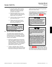
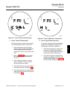
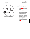
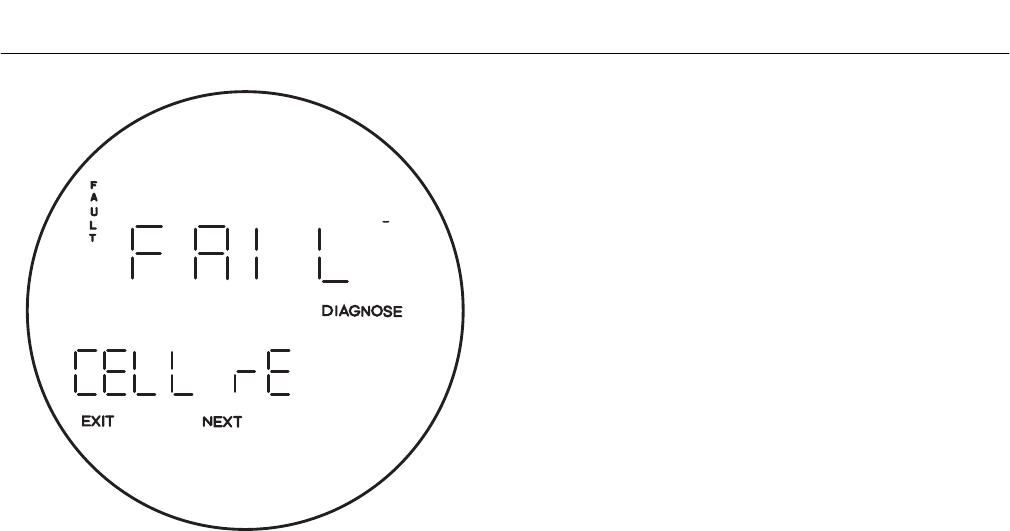
Figure 6-11. Fault 7, Reversed O
2
Cell
g. Fault 7, Reversed O
2
Cell
The O
2
cell connections are reversed. The
fault displays as shown in Figure 6-11.
1. Refer to Figure 6-4. Check the black
(to terminal 7) and white (to terminal 8)
wires for the proper placement. Rewire
if necessary.
2. Apply the low calibration check gas
(0.4% O
2
).
3. Using a multimeter, measure between
terminals 7(+) and 8(-). If the cell out-
put reading is negative, the O
2
cell
wiring is reversed.
4. If the wiring is correct, check if the mul-
timeter reading is the same as the
reading shown on the O
2
CELL mV di-
agnostics screen (see Section 3,
STARTUP AND OPERATION).
5. If the reading is different, the transmit-
ter electronics are faulty. Replace the
faulty analog or CPU board per para-
graph 5-1.
6


