


Instruction Manual
IB-106-5081, Rev. 1.0
May 2005
Rosemount Analytical Inc. A Division of Emerson Process Management Maintenance and Service 5-3
Model 5081FG
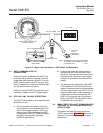
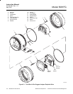
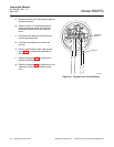
8. Connect the ribbon cable connector
between display board (12) and the
CPU board (11). Ensure the cable
connector is fully seated.
9. Reposition display board (12) on the
standoffs. Rotate the display board 90
degrees either way as desired.
10. Install and tighten all three screws (13)
and circuit end cap (14).
11. Tighten cover lock screw (15) until
cover lock (16) engages knurled sur-
face of circuit end cap (14).
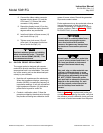
Use heat resistant gloves and clothing
when removing the probe. The probe
can be as hot as 1600°C (2912°F). This
can cause severe burns.
5-2 OXYGEN PROBE REPLACEMENT
The oxygen probe is designed with ceramic
materials to provide maximum life at elevated
temperatures and is not rebuildable. The condi-
tion of the sensing cell can be determined peri-
odically by two methods:
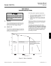
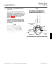
• Note the cell impedance at the electronics.
When the impedance displays a warning in-
dication (WARN), increase the frequency of
impedance readings. A cell with a sustained
high impedance indication (HI) indicates a
probe that is beyond its useful life.
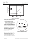
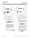
• Conduct a calibration check. Follow the
prompts provided by the electronics through
the process of flowing two calibration check
gases of known values. Record the generated
slope and constant values.
Probe replacement may be conducted online as
long as the process in which the probe is
mounted is operating at a negative, or slightly
positive, pressure. Refer to Section 6, TROU-
BLESHOOTING, for more information.
Do not install or remove probes from a
process where pressures are more
than a few inches of H
2
O positive
pressure. Hot gases may escape from
the stack and cause severe personal
injury.
Do not insert or withdraw a probe into
or out of a hot process faster than 1 in.
(25.4 mm) per minute or instrument
damage from thermal shock may
occur.
Also, ash, slag, or other materials can
build up on the probe body in some
applications. If this buildup is causing
difficulty when withdrawing the probe,
DO NOT FORCE. Rotate the probe
back and forth to attempt to loosen the
material on the probe body. Or, wait
until the process cools down and ac-
cess the buildup from inside the
furnace.
Refer to Table 8-1 for replacement probe part
numbers. Before replacing the probe, verify that
the reference air and calibration check gas lines
are turned off and disconnected from the probe.
5