


Instruction Manual
IB-106-5081, Rev. 1.0
May 2005
Rosemount Analytical Inc. A Division of Emerson Process Management Startup and Operation 3-1
Model 5081FG
SECTION 3
STARTUP AND OPERATION
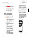
Install all protective equipment covers
and safety ground leads before
equipment startup. Failure to install
covers and ground leads could result
in serious injury or death.
3-1 GENERAL
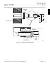
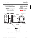
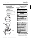
a. Verify Mechanical Installation
Ensure the Two-Wire In Situ Oxygen Ana-
lyzer is installed correctly. See paragraph
2-2 for mechanical installation information.
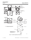
b. Verify Terminal Block Wiring
Ensure the wiring of both the oxygen probe
terminal block and Model 5081 Transmitter
terminal block is correct. Refer to paragraph
2-3 for electrical installation and wiring
information.
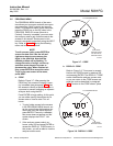
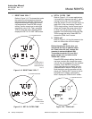
3-2 POWER UP
a. General
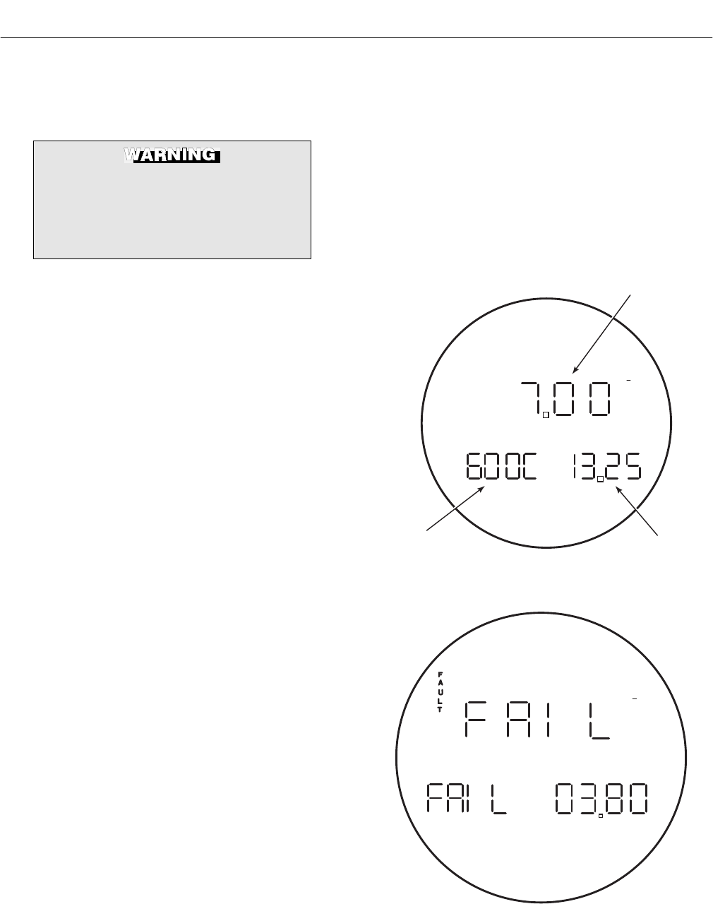
The Two-Wire In Situ Oxygen Analyzer dis-
plays the current oxygen reading on the
LCD face of the Model 5081 Transmitter.
The O
2
concentration, cell temperature, and
4-20 mA output current are displayed as
shown in Figure 3-1. This and other infor-
mation may also be accessed using
HART/AMS.
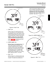
b. Startup Display
When the probe is first inserted into the
stack, some time is required until minimum
operating temperatures [550°C (1022°F)]
are reached. Some time is also required for
the electronics to reach an operating state.
Therefore, when the unit is first powered up,
a faulted operation display as shown in Fig-
ure 3-2 may be displayed by the transmitter
until the probe operating temperatures are
reached and the electronics are working
properly (approximately 5 minutes).
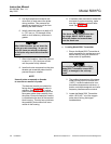
c. Operating Display
After the probe has reached operating
temperatures, the Model 5081 Transmitter
display should look similar to Figure 3-1.
The display will now track the O
2
concentra-
tion, cell temperature, and 4-20 mA output
current.
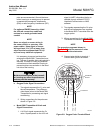
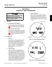
%
mA
4-20 mA OUTPUT
26020007
O CONCENTRATION
2
CELL
TEMPERATURE
Figure 3-1. Normal Operation Display
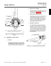
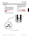
%
mA
26020008
Figure 3-2. Faulted Operation Display
3