


Instruction Manual
IB-106-5081, Rev. 1.0
May 2005
3-2 Startup and Operation Rosemount Analytical Inc. A Division of Emerson Process Management
Model 5081FG
3-3 REESTABLISHING PROPER CALIBRATION
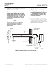
CHECK GAS FLOW RATE
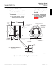
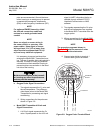
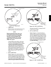
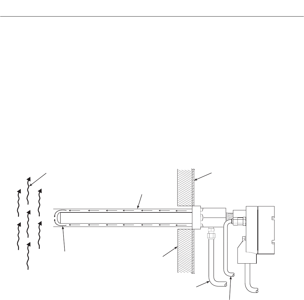
The calibration check gas flow must be enough
to ensure no combustion flue gases mix with the
calibration check gases and only clean, good
calibration check gas surrounds the cell without
expending excess gas (Figure 3-3). Monitor the
O
2
concentration using an IRC or HART Com-
municator. Set the calibration check gas flow
rate as follows:
NOTE
Only set the calibration check gas flow
rate at startup. It is not necessary to
perform this procedure for each cali-
bration check.
a. Adjust the calibration check gas flow to 5
scfh (2.5 L/min.) to ensure the cell is sur-
rounded by calibration check gas. Due to
the cooling effect of the gas, the cell tem-
perature will decrease slightly, causing the
O
2
concentration to drop. Once the elec-
tronics compensates for this effect, the O
2
concentration will stabilize.
b. Next, slowly reduce the calibration check
gas flow until the O
2
concentration changes,
which indicates that the calibration check
and flue gases are mixing. Increase the flow
rate until this effect is eliminated.
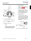
REFRACTORY
FLUE GAS
CELL
STACK OR DUCT
METAL WALL
PROTECTIVE
TUBE
CALIBRATION
GAS
CALIBRATION
CHECK GAS LINE
REFERENCE
AIR LINE
26020062
Figure 3-3. Proper Calibration Check Gas Flow Rate