


Instruction Manual
IB-106-5081, Rev. 1.0
May 2005
Rosemount Analytical Inc. A Division of Emerson Process Management Description and Specifications 1-5
Model 5081FG
TWO-WIRE IN SITU
OXYGEN ANALYZER
TERMINATION IN
CONTROL ROOM
24 VDC
POWER
SUPPLY
+
INTRINSIC
SAFETY
BARRIER
(OPTIONAL)
37240002
ASSET MANAGEMENT
SOLUTIONS
4-20 mA OUTPUT
(TWISTED PAIR)
HART
MODEL 275/375
HAND HELD
INTERFACE
MODEL 5081
TRANSMITTER
OmV
SIGNAL
2
TEMPERATURE
mV SIGNAL
REFERENCE
AIR LINE
CALIBRATION CHECK
GAS LINE
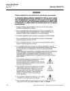
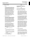
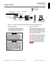
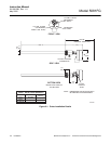
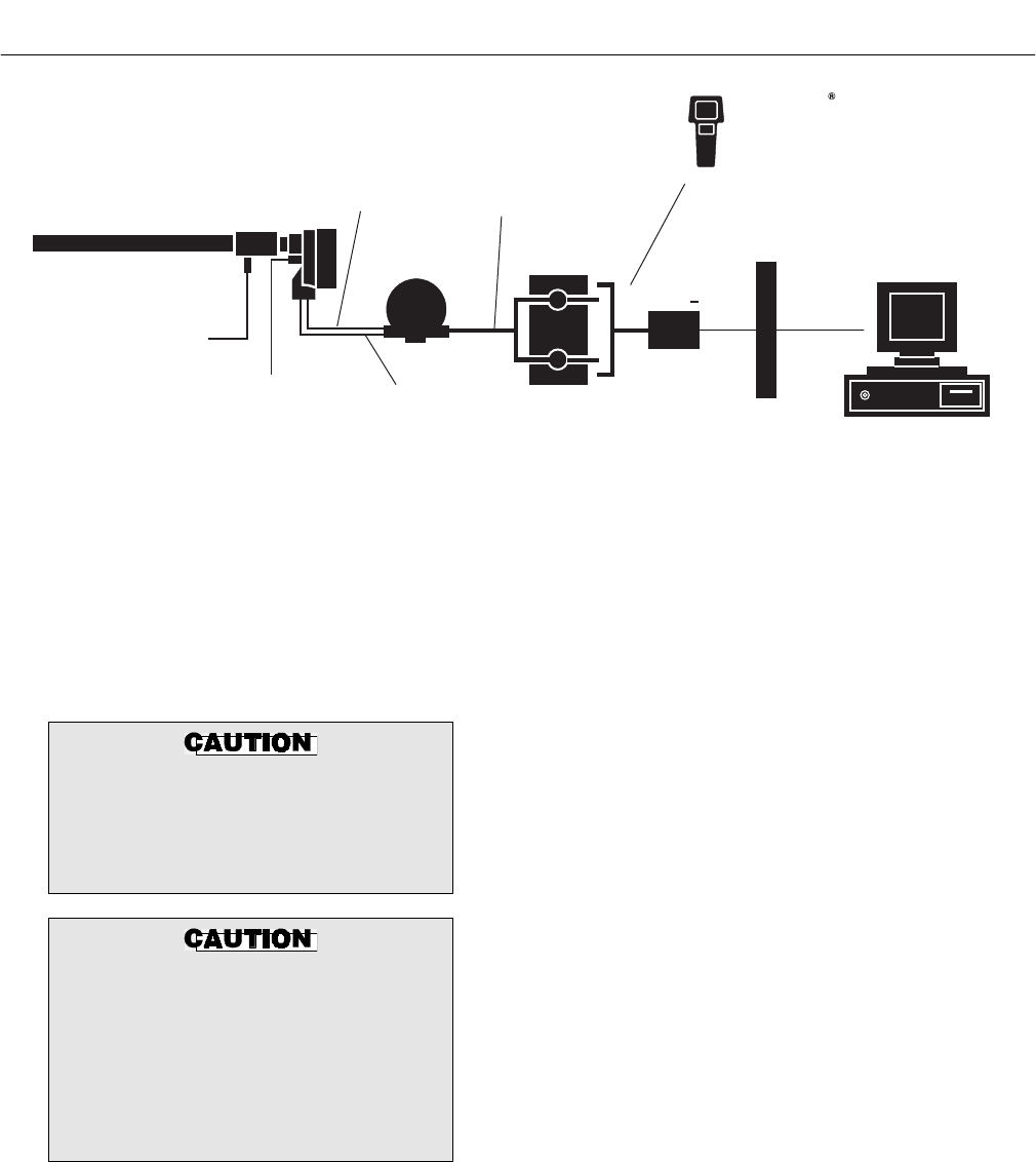
Figure 1-2. Two-Wire In Situ Oxygen Analyzer HART Connections and AMS Application
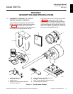
e. Handling the Analyzer
The probe was specially packaged to pre-
vent breakage due to handling. Do not re-
move the padding material from the probe
until immediately before installation.
It is important that printed circuit
boards and integrated circuits are
handled only when adequate antistatic
precautions have been taken to pre-
vent possible equipment damage.
The oxygen probe is designed for in-
dustrial applications. Treat with care to
avoid physical damage. The probe
contains components made from ce-
ramic, which are susceptible to shock
when mishandled. THE WARRANTY
DOES NOT COVER DAMAGE FROM
MISHANDLING.
f. System Considerations
Prior to installing your Rosemount Analytical
Two-Wire In Situ Oxygen Analyzer, make
sure you have all the components neces-
sary to make the system installation. Ensure
all the components are properly integrated
to make the system functional.
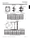
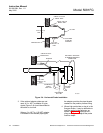
After verifying that you have all the compo-
nents, select mounting locations and deter-
mine how each component will be placed in
terms of available line voltage, ambient
temperatures, environmental considera-
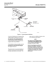
tions, convenience, and serviceability. Fig-
ure 1-2 shows a typical system wiring. A
typical system installation is illustrated in
Figure 1-3.
1