


Instruction Manual
IB-106-5081, Rev. 1.0
May 2005
Rosemount Analytical Inc. A Division of Emerson Process Management Installation 2-11
Model 5081FG
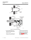
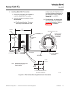
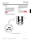
4-20 mA (+)
4-20 mA (-)
CELL AND
THERMOCOUPLE
4-20 mA
26020005
GROUND
THERMOCOUPLE + (GY)
CELL - (WH)
THERMOCOUPLE - (RD)
CELL + (BK)
EARTH
GROUND
TERMINALS
TERMINAL
BLOCK (TB1)
FACTORY-INSTALLED
JUMPER
PROBE CABLE
SHIELD
CONDUITS
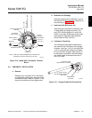
NOTE:
RUN CELL AND THERMOCOUPLE SIGNALS IN
SEPARATE CONDUIT FROM 4-20 mA LINE.
12
3
5
6
7
8
9
11
12
13
14
15
16
10
4
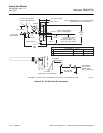
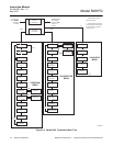
Figure 2-10. Model 5081 Transmitter Terminal
Block
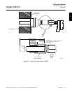
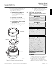
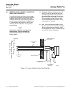
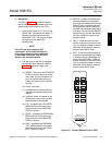
2-4 PNEUMATIC INSTALLATION
a. General
Reference air is required for O
2
calculation,
and calibration check gas is required during
a calibration check. Refer to Figure 2-11 for
the gas connections on the oxygen probe.
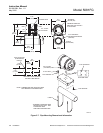
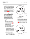
b. Reference Air Package
After the oxygen probe is installed, connect
the reference air set. Install the reference air
set according to Figure 2-12.
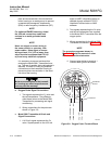
c. Instrument Air (Reference Air)
Instrument air is required for reference. Use
10 psig (68.95 kPa gage) minimum, 225
psig (1551.38 kPa gage) at 0.2 scfh (100
ml/min.); less than 40 parts-per-million total
hydrocarbons. Regulator outlet pressure
should be set at 5 psi (35 kPa).
d. Calibration Check Gas
Two calibration check gas concentrations
are used with the Two-Wire In Situ Oxygen
Analyzer: Low Gas - 0.4% O
2
and High Gas
- 8% O
2
, each with the balance in nitrogen.
Do not use 100% nitrogen. See Figure 2-11
for the probe connections. Set both calibra-
tion check gases at the same flow rate: 5
scfh (2.5 L/min).
1/4 TUBE FITTING
(REFERENCE AIR PORT)
26020006
1/4 TUBE FITTING
(CALIBRATION CHECK
GAS PORT)
REFERENCE
AIR VENT
Figure 2-11. Oxygen Probe Gas Connections
2