


Appendix A: AMX Lighting Curves
51
RE-DM4 and RE-DM6 RADIA Eclipse Dimmer Modules
The RDM-SWM and RDM-ZC modules uses the third dimmer characteristic of switching a relay on or off.
The relay turn on level indicates the level at which the switch module turns on. This is typically set to 1. A
notable exception is Curve N, which is set at Level 9.
The RDM-FDB module uses a combination of the first and third characteristics to send a variable high-voltage
output along with a single switched output. The RDM-FDB module is a combination of two devices in a single
package. One device is an incandescent dimmer like the RDM-INC, and one device is a relay like the RDM-
SWM. These devices combine to switch power on and off to a ballast, and at the same time deliver a high-
voltage reference signal to the dimming ballast. The RDM-FDB module also works with several lighting
interfaces made by companies other than AMX.
The RDM-HDC module uses a combination of the second and third dimmer characteristic to send a variable
low-voltage control signal along with a single switched output. This module is commonly used for control of
dimmable fluorescent ballasts.
Curves can be used for energy-saving applications where the high end needs to be trimmed to reduce voltage
to the lamps and thereby increase lamp life. They can also be used to reduce the dimming range of some
fluorescent ballasts, which can prevent premature failure of the ballasts and lamps.
The AMX Lighting system now offers over 12 ways to alter the performance of the lighting fixture by digitally
changing the way the dimmer responds. Using the RDM-HDC module, for instance, to control an 0-10 volt
ballast applied to a single compact fluorescent light fixture might 'look' better when dimmed using one curve
instead of another. After the furniture is installed, the designer may decide that a different curve applied to
certain fixtures has a better 'feel.' It is now possible to apply many new curves to all the AMX Lighting
dimmers using simple commands. Designers and specifiers have much more control over the look and feel of
their designs using the AMX Lighting system. Installers will have greater ability to temper the output of a
dimmer to avoid problems.
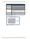
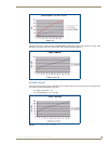
As the dimming level increases the output voltage increases. The dimmer goes smoothly from 0 to 120 volts
output. This is the most common curve used in dimming applications.
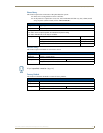
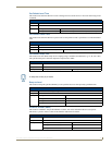
Relay turn on level = 1%
Dimming Range = 0 - 120 VAC.
Curve Configuration
Each Radia dimmer maintains non-volatile configuration information that is necessary to the operation of the
dimmer such as presets, curves, ramp times, etc. The configuration can be uploaded and downloaded from the
dimmer for the purposes of providing a user interface to ease the configuration process and for archival
purposes.
Curves
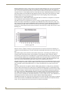
Curves are used to define the relationship between the dimmer's level and the actual output voltage. For
example, the typical curve (curve 1) is a linear mapping of the dimmer's input level to the dimmer's output
level which means a value of 10% in the input level will result in a 10% output voltage.
The selection of which curve to use is purely a function of the type of electrical load connected to the dimmer's
output. For example, an incandescent load would typically use curve 1 or curve 2 and a Prescolite fluorescent
ballast would use curve 4.
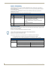
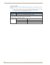
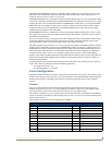
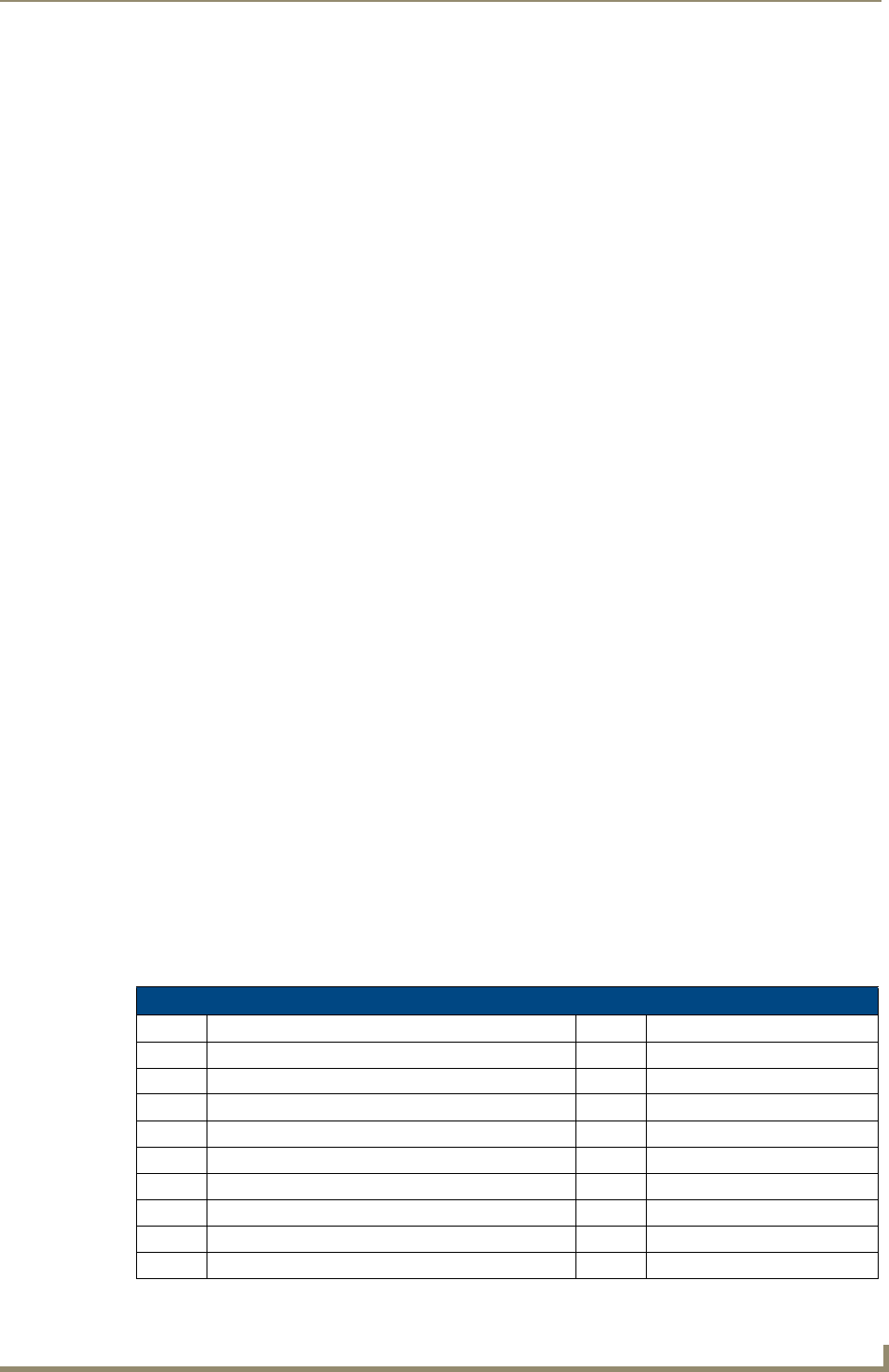
The table below summarizes the curves supported by the Radia:
Curves
Symbol Description Symbol Description
1 Standard Dimming Curve A S-curve #1
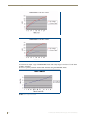
2 Economical Dimming Curve (0-90%) B Log-curve #1
3 0-10 VDC Curve for Advance MK VII, Motorola Helios C Log-curve #2
4 0-12 VDC Curve for Prescolite Intelect D S-Curve #2
5 Advance Mark VII E 25% off
6 Advance Mark VII F Always ON
7 12% roll off N 10% off
8 19% roll off for Lutron FDB O Always off
9 33% roll off for Lutron FDB R Reverse Linear