


Installation
22
RE-DM4 and RE-DM6 RADIA Eclipse Dimmer Modules
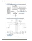
Configuring and Connecting AxLink
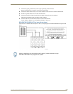
On all AMX Lighting controllers, DIP switch SW1 sets the AxLink device number. The device number is
determined by the value of all the switch position settings. The following table shows the SW1 DIP switch
positions and their values.
The device number assignment range is 1 through 255.
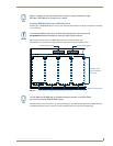
1. Power off the enclosure unit at the breaker panel.
2. Locate the SW1 DIP switch (AxLink ADDRESS) on the controller circuit card and set the device
number, using the values shown in the proceeding table.
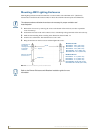
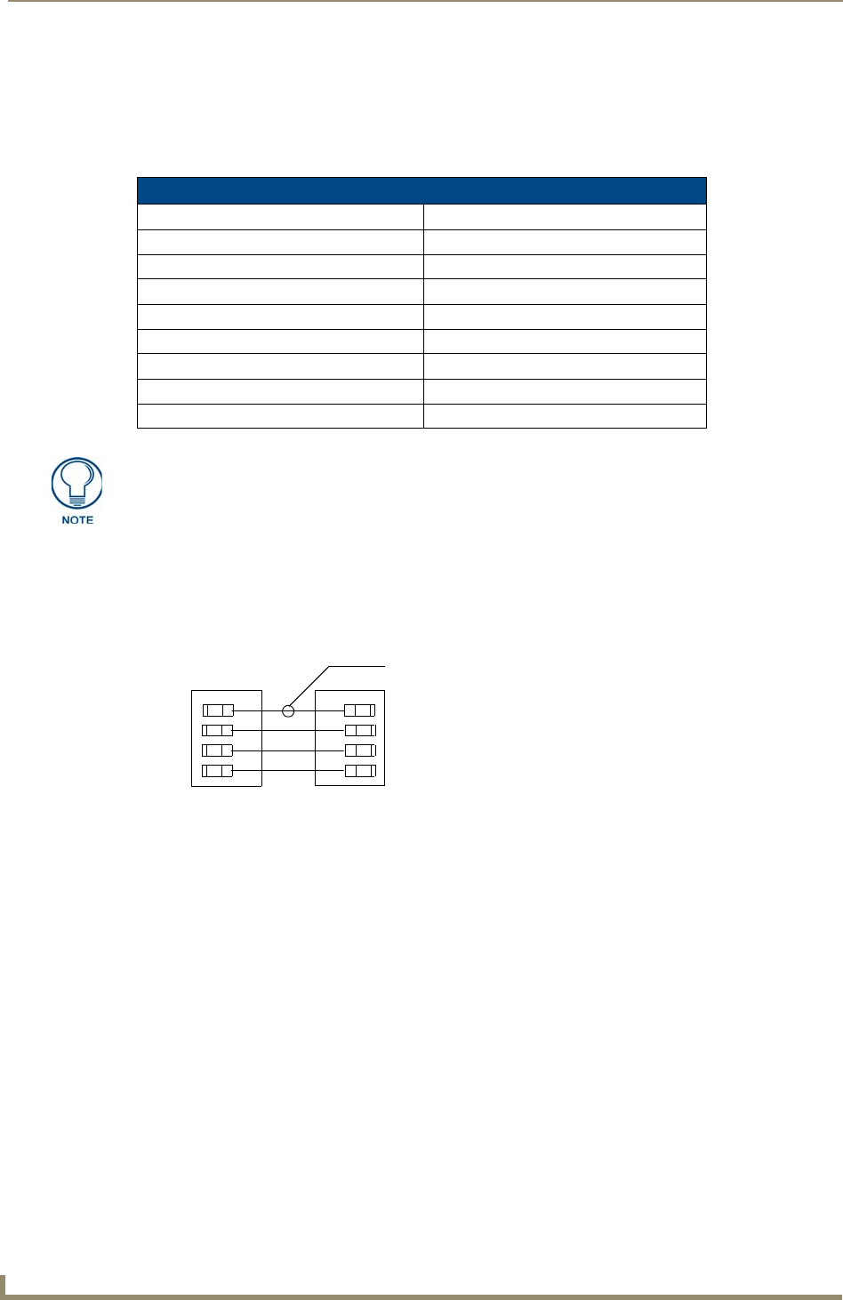
3. Connect the four-pin AxLink male connector into the four-pin female AxLink connector on the controller
circuit card. FIG. 27 shows how to wire the AxLink connector to a Central Controller system.
4. Apply power to the controller module at the breaker panel.
5. Radia v3.xx and higher constantly read the AxLink address switch.
Power does not need to be reset or cycled after changing the AxLink address.
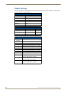
SW1 DIP Switch Setting Values for AxLink
Position Value
11
22
34
48
516
632
764
8 128
Turning off all switches invokes "Installer Test Mode": all lighting circuits at 100%.
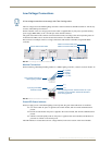
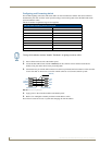
FIG. 27 AxLink wiring diagram
Central ControllerAxLink connector
+12V
AXP/TX
AXM/RX
GND
+12V
AXP
AXM
GND
(optional)