


Appendix A: AMX Lighting Curves
50
RE-DM4 and RE-DM6 RADIA Eclipse Dimmer Modules
Dimmer manufacturers follow or adopt a level to output ratio called the Square Law curve. It is an exponential
relationship between percentage of light perceived and the percentage of light measured. The Square Law
Curve is a presumed relationship between perceived illuminance and measured illuminance. The Radia Eclipse
controller's Curve 1 is a basic Square Law Curve. From this basic curve, AMX has developed a set of curves
other than standard to accommodate the many different properties of the various loads connected to a AMX
dimmer. Multiple curves provide a user with multiple ways to control lighting. This provides lighting
designers with a more powerful lighting tool.
To demonstrate how a AMX dimmer actually performed under real conditions, we adopted a set of uniform
tests to display the output characteristics of a dimmer.
The AMX test fixture for incandescent tests was set up using a constant Voltage feed of 120 VAC to the
dimmer. The output of the dimmer was connected to (6) 100W GE lamps with a total load of 5 Amps. All
fluorescent tests were done using the RDM-HDC module connected to a (2) lamp Advance Mark VII ballast
using T-8 rapid start lamps. These curve plots are to be used as a relative guide to determining optimum
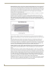
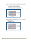
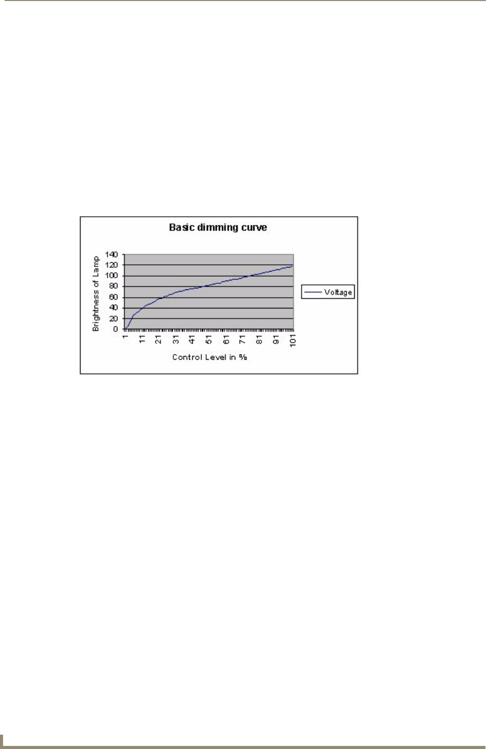
performance. Actual field performance and measurements will be similar but not equal. FIG. 38 shows a basic
dimming curve.
Each curve allows a dimmer to change its output characteristics in relation to the amount of dimming. For
example, the standard dimming curve at 50% could make a light brighter than another curve which was also at
50%.
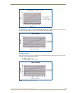
Each AMX Lighting control channel has three dimmer characteristics; AC dimming, DC dimming, and
switching. These are the three primary control methods for most lighting systems worldwide. The first
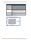
characteristic is the output level in volts RMS. This is represented by the following Curve charts showing the
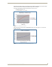
Y-axis in (Dimmer) Output Level in Volts RMS (0-120VAC). The second characteristic is displayed on the
second curve chart with the (Dimmer) Output Level in Volts DC (0-12VDC). The third characteristic is the
turn on level for the switched (relay) aspect and is noted in text as the Relay Turn On Level.
This third characteristic controls the RLY output of the RDM connections on the RE-DM4. Previous versions
of Radia would turn on the RLY outputs at INPUT (from control system) levels of 1 or above. Radia Eclipse
turns on the RLY output at the OUTPUT level of 1, so that it can effected by curve choices and low end
settings.
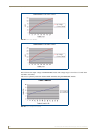
These three characteristics are applied to different AMX Lighting dimmers to change the way the dimmers
perform. The first characteristic most often used for incandescent dimming requires a variable high-voltage
output to one Hot wire connected to the incandescent lamp. The curve determines the amount of high-voltage
applied to the dimmer's output in relation to the control level. The second dimmer characteristic applied to
low-voltage output of the AMX RDM-HDC module is commonly used for fluorescent ballasts that require a
low-voltage control signal to vary the output of the ballast. The third dimmer characteristic merely turns a
relay on or off at a specified level. This third characteristic is set at an output level of 1. The combinations of
these characteristics allow AMX to tailor the outputs of different AMX Lighting dimmers.
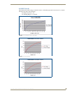
The RDM-INC module only requires the first characteristic that controls the high voltage output of a dimmer.
All the internal dimmers in the RE-DM4 and RE-DM6 also use the first characteristic to determine dimmer
output. All curve diagrams that use this characteristic are labeled in Volts RMS.
FIG. 38 Basic dimming curve