


AMX RADIA Lighting Programming
34
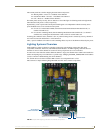
RE-DM4 and RE-DM6 RADIA Eclipse Dimmer Modules
Programming Commands
The AMX Lighting system uses four main types of programming commands: Setup, Recording, Status, and
Operation commands. The following description applies to the AxLink Command Structure.
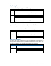
Setup commands
These types of commands are global commands sent to Pack #1 that affect the entire network.
These commands are used to set the default values and parameters that are typically entered at the startup of
the system and not changed. If certain commands are issued with a time value associated then the AMX
Lighting system will use an available default value determined at setup.
The commands for recording and recalling presets use these defaults, as do ramping operations. Curve settings
are setup commands done on a individual channel basis and are not global.
Curves are set in the beginning and do not need to be changed unless the loads also change.
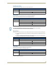
Recording commands
These commands send preset data to the AMX Lighting memory chip. All recording and setup commands are
stored in non-volatile memory. These commands are also used to store presets, assign presets for dry closure
recall, and erase stored presets.
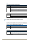
Status commands
Status commands allow a user or a program to get data from the lighting system and act on that information.
This feature gives a computer the ability to perform interactive processes with the AMX Lighting system.
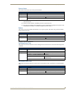
Operation commands
The operational commands category, the largest category used by the AMX Lighting system, is used for real-
time lighting control and setup of scenes prior to programming presets. Operational commands recall, ramp,
and set levels for dimmers. They can also be used for remote operation of the dry closure contact.
Control Curves and Low-End Settings
The market currently has a great selection of new lamp and ballast options. Each one has properties and
dimming characteristics that present a new challenge for the dimmer manufacturer to provide an appropriate
dimmer. What was designed as a standard incandescent dimmer must now be able to control electronic ballast,
incandescent lamps, low voltage track lighting, and a host of new transformers. One way to solve many of
these problems is to apply different control curves to each dimmer and to provide a variable low-end cut-off
point.
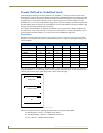
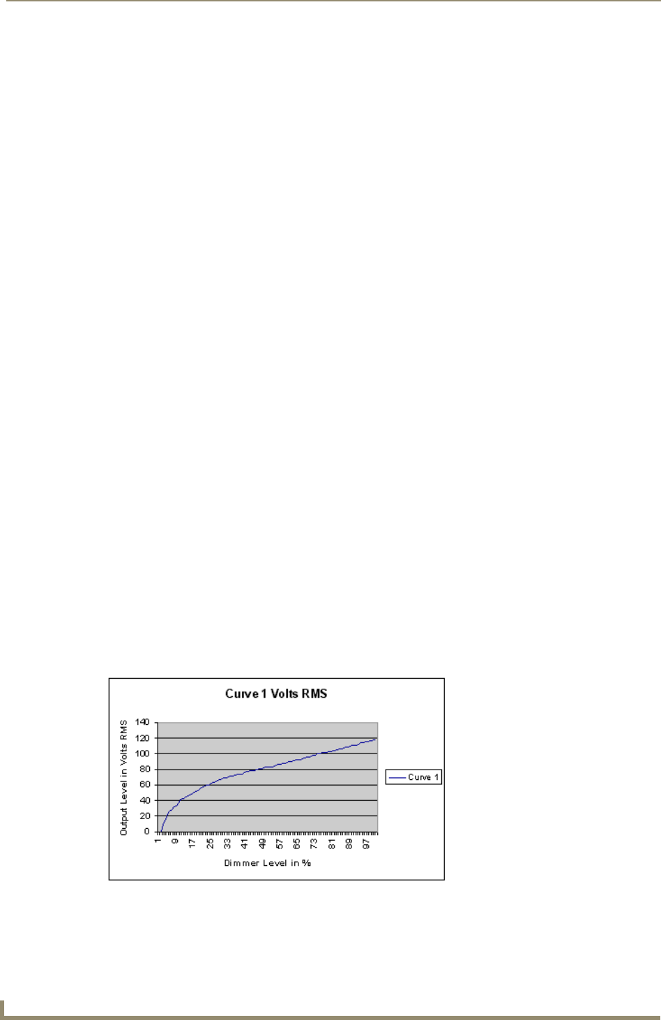
A dimming curve is a graphical or electronic representation of the amount of control that must be applied to a
dimmer in relation to the dimmer output. This is much like a directional map that the controller follows. The
amount of control is typically measured in percent; from an Off-state of level 0 to an On-state at level 100.
Dimmer output is measured in volts. A graphical representation of a dimming curve is usually the percentage
of dimming in relation to the output voltage (RMS) of the dimmer connected to a standard load. FIG. 37 shows
a sample dimming curve.
Sometimes a fixture or lamp has a problem dimming down to a low range. When this happens, the lights can
flicker and cause unwanted dimming performance.
FIG. 37 Sample dimming curve