


Appendix A: AMX Lighting Curves
49
RE-DM4 and RE-DM6 RADIA Eclipse Dimmer Modules
Appendix A: AMX Lighting Curves
Overview
Thousands of different lighting fixtures with unique shapes and styles exist, all designed to do something
visibly different with light. Any one of those fixtures in a hundred different locations could produce a different
lighting effect. Two identical lights in different locations could produce different reflections and shadows.
For instance, consider a situation where low-voltage track lights are mixed with compact fluorescent down
lights to illuminate a hallway with pictures. Under normal dimming conditions, the two different light sources
would dim differently and possibly require individually set dimmers to accomplish uniform lighting at
different levels. An Up or Down button on a wall control panel would dim both sources at a common rate, but
the lamps and fixtures would dim at different rates due to the lamp and ballast characteristics. The track light
may stay bright for an extended period and then rapidly dim to nothing while the fluorescent lamp dims
smoothly to a point and then abruptly shuts off. The combined effect produces an uncoordinated scene change.
An unwanted feature of dimmable fluorescent ballasts and low-voltage electronic transformers is their
tendency to cause the lamps to flicker when dimmed to low levels. The normal way to avoid this is to use
presets that are not dimmed below the fixture's threshold or to use any low end trim feature provided by the
ballast or transformer manufacturer. Problems arise when the performance of the dimmer does not match the
performance of the dimmable ballast. The AMX Lighting system now gives the user the ability to change the
performance of the dimmer to avoid problems.
Many types of track lights and dimmable ballast only have a limited dimming range for the dimmer to work
with. In a dimming range of 0 to 120 volts AC, many lamps do not start to dim until fewer than 100 volts is
applied. Lamps often do most of their dimming between 40 and 100 volts. Dimmers designed to increment
voltages from 0 to 120 volts can be wasted on lamps that do not even respond to 50% of the dimmer's output.
Some lamps are more sensitive to voltage changes at the low end and can accommodate many degrees of
dimming, but standard dimmers tend to rush past the lamp's sensitive range and occasionally linger in an
unusable range.
Slowly turning a lamp on can be a very different effect than slowly dimming that same lamp off. Some light
sources require a minimum level to turn on. Once these lamps are on, they can be dimmed down to lower light
levels. At the same time, most common dimmers are built to dim at a uniform rate, regardless of the individual
characteristics of each lamp or the number of lamps.
The properties and dimming characteristics of each new lamp and ballast on the market present a new
challenge to the dimmer manufacturer to provide an appropriate dimmer. What was designed as a standard
incandescent dimmer must now be able to control electronic ballasts, incandescent lamps, transformered low-
voltage track lighting, and a host of electronic transformers.
One way to solve many of these problems is to tailor the style of dimming for each individual dimmer in a
system. The way to do this is to apply different dimming curves to each dimmer and to provide a variable low-
end cut-off point.
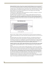
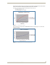
A dimming curve is a graphical or electronic representation of the amount of control to a dimmer in relation to
the dimmer output. It is like a directional map followed by the dimmer. The amount of control is typically
measured in percentages, from an off-state at level 0 to an on-state at level 100. Dimmer output is measured in
volts. A graphical representation of a dimming curve is usually the percentage of dimming in relation to the
output voltage (RMS) of the dimmer connected to a standard load.
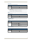
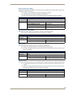
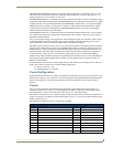
AMX Lighting curve changes are implemented by a command to the AMX Lighting device. This example
would set dimmer channel #1 to curve 6. The available curves that can be sent to the AMX Lighting controller
are: 1, 2, 3, 4, 5, 6, 7, 8, 9, A, B, C, D, E, N, O, R, and F.
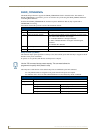
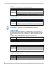
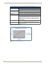
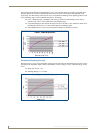
The Radia Eclipse controllers can employ a low-end cut-off that allows the dimmer to turn on to a specified
level or to dim down to no less than a specified level. This level at which the dimmer turns on is called the Low
End Setting. This is also used to turn a light off at the low end point when dimming down from a bright level.
A low end setting of 25 applied to the standard dimming curve would prevent the fixture from being dimmed
below Level 25. From an off condition, the same fixture would dim up to Level 25 and hold that level until the
dimming curve directed the level higher.
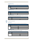
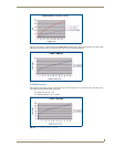
If a fixture flickers just before it goes out, then the Low-End Setting can be used to avoid the unusable
dimming range. Setting the Low-End Setting to just above the level where flickering problem starts will
prevent the dimmer from allowing the flicker to be seen.