


Installation
17
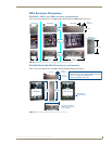
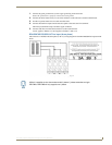
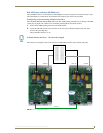
RE-DM4 and RE-DM6 RADIA Eclipse Dimmer Modules
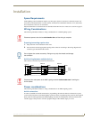
1. Connect the green ground wire(s) to the copper ground lug on the enclosure.
Ensure the ground wire is properly connected to earth ground.
2. Connect the white neutral wire(s) to one of the terminals on the enclosure's neutral terminal block.
3. Provide a separate neutral wire for each controlled zone.
4. Connect the black line input from the electrical panel to the enclosure's line terminal.
The line input terminal accepts a 0 AWG copper conductor.
5. Connect load lines from the electrical devices to the Load terminals.
Load 1 applies to dimmer 1, Load 2 applies to dimmer 2, and so on.
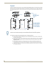
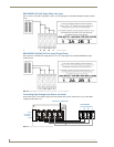
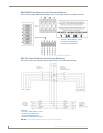
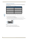
RDA-ENC6B 120/208 VAC line input (three phase)
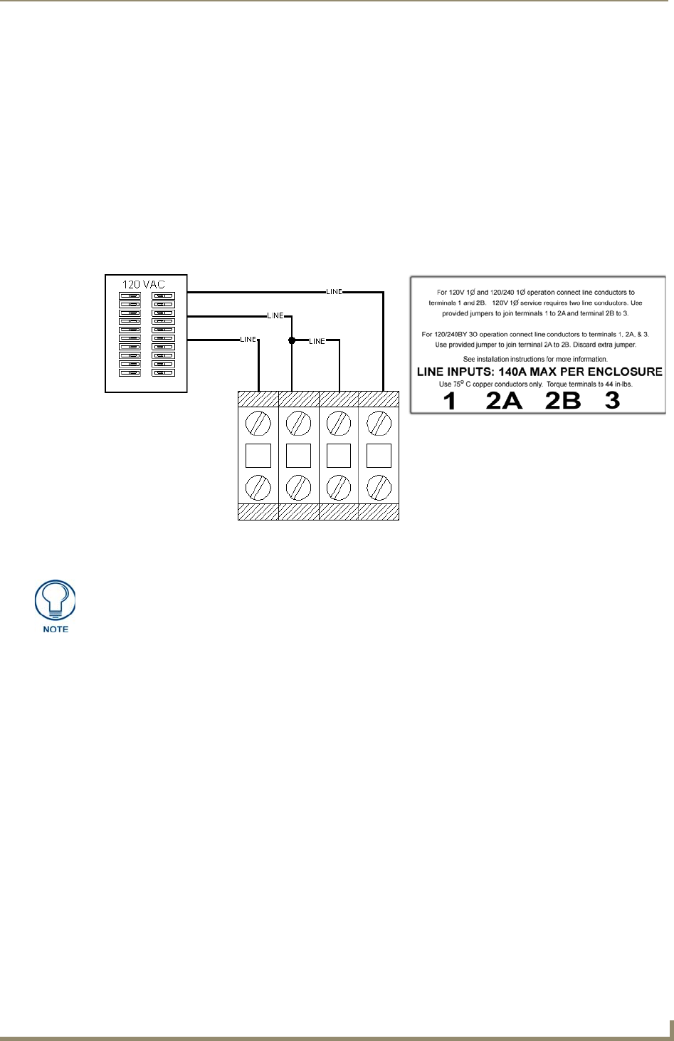
FIG. 20 shows a 120/208 VAC three-phase (4 W + G) wiring diagram for the RDA-ENC6B line input terminal
block.
FIG. 20 RDA-ENC6B 120/208 VAC three-phase (4 W + G) wiring diagram
12a2b3
While it is possible to wire the enclosure with 3-phase Y, please remember a single
RE-DM4 or RE-DM6 will only support one Y-phase.