


Installation
20
RE-DM4 and RE-DM6 RADIA Eclipse Dimmer Modules
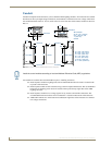
Low-Voltage Connections
The low-voltage area in the AMX Lighting controllers contain connections and DIP switches for AxLink, dry
closures, and module jack connectors.
On the controller cards, low-voltage power for the board is supplied either by line power, optional auxiliary
power supply (RDA-PSM), or the +12 VDC pin on the AxLink connector.
The green status LED on the controller circuit board also blinks, according to the current operating status of
AxLink and red LEDs, one for each of the external connectors for additional modules.
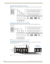
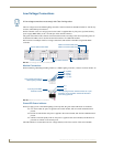
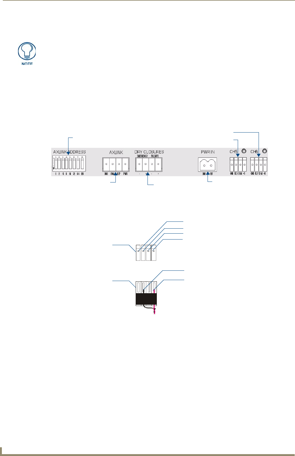
FIG. 24 shows an example of the low-voltage connections, DIP switches and LEDs using the RE-DM4
controller.
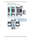
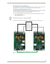
Module Connections
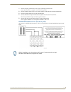
When connecting a dimming/switching module to a AMX Lighting controller, connect it as shown in FIG. 25.
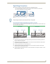
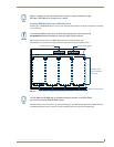
Green LED Status Indicator
When you apply power to the AMX Lighting Control System, the green status LED notes its conditions:
It is on full when AC power is applied to the control module, and no AxLink communication is
present.
It blinks on and off when AC power is applied to the control module, and AxLink communication is
present.
It blinks on and off rapidly when no AC power is applied to the control module, and the board is
powered via AxLink or Aux In DC power.
The LED indicator is located above the low voltage terminal, in the lower section of the control module.
All low-voltage connections must comply with Class 2 wiring codes.
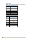
FIG. 24 Low-voltage connections and DIP switches
FIG. 25 Module connection to a controller card
AxLink address DIP switch
Module connector/LED (CH6)
Dry contact closures
Auxiliary power IN
Module connector/LED (CH5)
AxLink connector
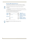
4-pin module connector on
AMX Lighting controller
4-pin plug from RDM-
controller module
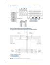
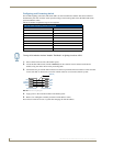
Pin 4 (GND)
Pin 3 (RLY)
Pin 2 (DIM)
Pin 1 (+12V)
3 (-)
1 (+)
The 4-pin plug from the module connects to a 4-pin
connector on the controller module with the black
cover facing upwards.