


AMX RADIA Lighting Programming
32
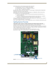
RE-DM4 and RE-DM6 RADIA Eclipse Dimmer Modules
Presets: Defined vs. Undefined Levels
Understanding the meaning of the terms "defined" and "undefined", as used in the context of levels in the
Radia lighting system, is helpful. Each dimmer on the Radia has a TRUE/FALSE status associated with it that
is referred to as "defined". The state of the defined status is used when saving presets so that the Radia knows
which dimmers are to be affected when the preset is recalled. Upon power-up, all the dimmers are in the
undefined state. As soon as any of the dimmers changes state (i.e. the level changes), the dimmer automatically
becomes defined. Upon recording a preset, the Radia will save all of the dimmer levels that are defined at that
time and only affect those when the preset is recalled.
For example, if all the dimmers are undefined and dimmers 1 and 3 get their levels changed, the Radia will
save the levels of 1 and 3 only when told to record preset 7. When preset 7 is recalled, only dimmers 1 and 3
will be adjusted. The other dimmers (2, 4, 5 and 6) are said to be undefined for that preset.
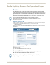
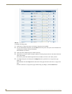
Preset Status
Channels 1-128 reflect the current status of active presets. A preset is "active" for as long as its associated
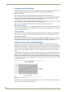
dimmers (circuits) remain at the levels associated with the preset. For example, assume the following presets
exist in the Radia:
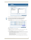
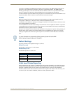
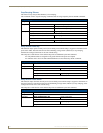
Also, the configuration of the Radia is such that dimmers 1-3 are controlling lights in room A (a conference
room) and dimmers 4-6 are controlling lights in room B (another conference room). In each of these room is a
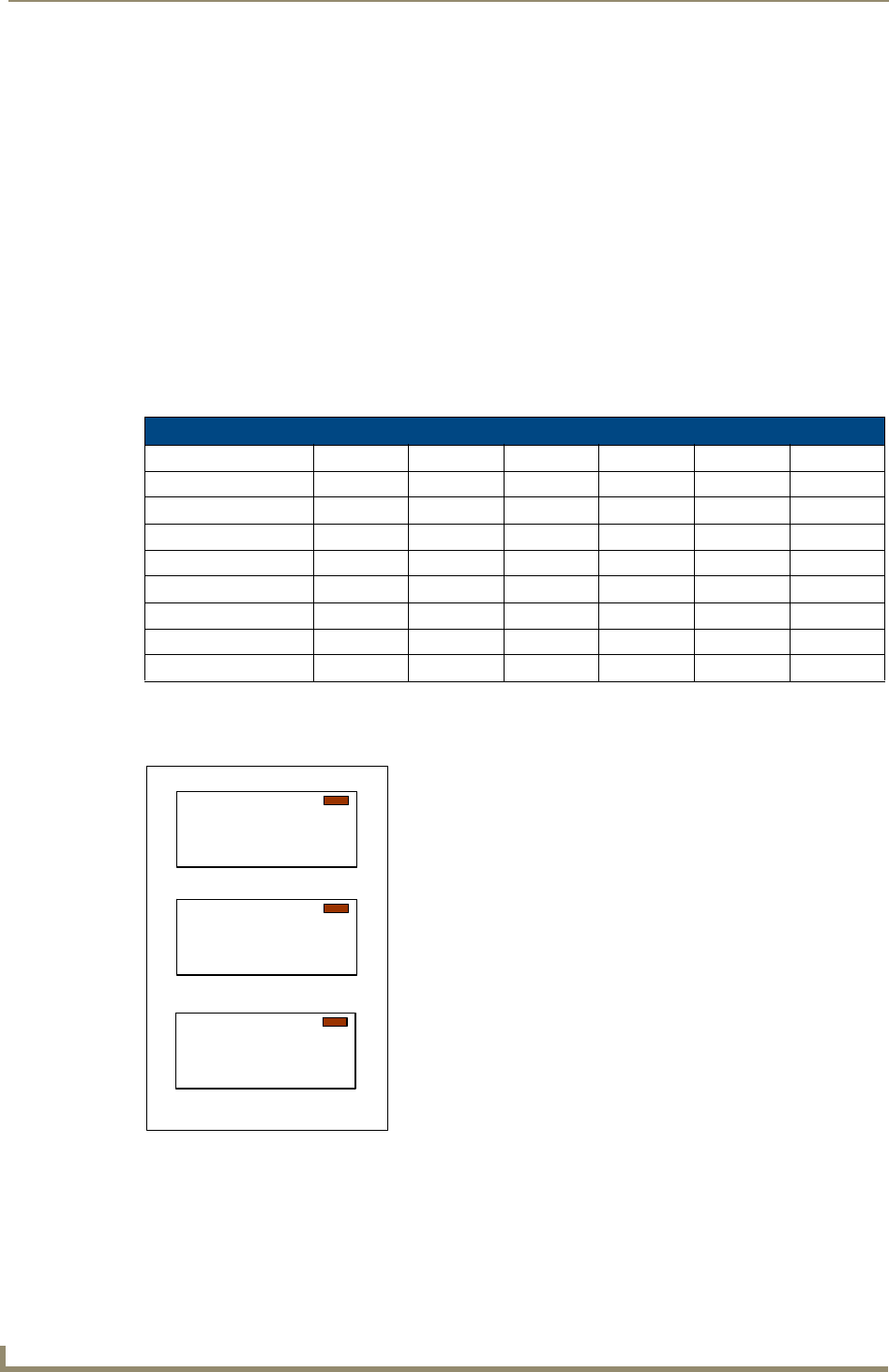
3-button wall-mounted control panel that provides control of the local lights:
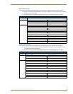
The room A panel has the following mapping between buttons and presets and feedback:
Meeting Mode -> Preset 1 -> Feedback from channel 1
Presentation Mode -> Preset 2 -> Feedback from channel 2
Off -> Preset 3 -> Feedback from channel 3
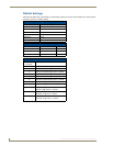
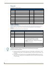
Preset #
Preset #
Dimmer #1 Dimmer #2 Dimmer #3 Dimmer #4 Dimmer #5 Dimmer #6
1 – Meeting (A) 100% 50% 100%
2 – Presentation (A) 50% 25% 50%
3 – Off (A) 0% 0% 0%
4 – Meeting (B) 100% 50% 100%
5 – Presentation (B) 50% 25% 50%
6 – Off (B) 0% 0% 0%
7 – Cleaning (A&B) 100% 100% 100% 100% 100% 100%
8 – Night (A&B) 0% 0% 0% 0% 0% 0%
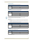
FIG. 35 Example - 3-button wall-mounted control panel
Meetin
g
Mode
Presentation
Mode
Off
Meeting Mode
Presentation Mode
Off