


Page 5
(2) Temporarily connect hoist to power source.
(3) Operate á button briefly to determine direction of
hook travel.
(4) If hook raises, phase is correct. Turn power off and
make temporary connections permanent.
(5) If hook lowers, hoist is “Reverse Phased”. TURN
POWER OFF and correct by interchanging any two leads at
power source connection. Do not change internal wiring of
hoist.
c. Check Limit Switch Operation.
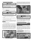
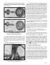
(1) A block operated upper limit stop (Figure 2-2) is
furnished as standard equipment. This limit stop is factory
set to stop lower block in its high position and guard against
over-travel and possible damage to hoist. (Note mounting
position of floating lever for 3 and 5 ton hoists.) No adjustment
can be made. Limit switch operation should be tested when
hoist is installed. Move hook to a low position by depressing
push button marked â. Now depress button marked
áá
áá
á to
raise hook. While hook is traveling upward, manually (or with
an extension pole) raise limit stop mechanism (Figure 2-2).
b.
Check Push Button Operation and Phasing.
On three phase hoists it is possible to have “Reverse
Phasing” causing the lower block to lower when the
áá
áá
á button is depressed. When this condition exists,
the automatic limit stop switch is inoperative and
hoist operation will be dangerous.
WARNING
If any push button binds or sticks in any position —
DO NOT TURN POWER ON — determine the cause
and correct the malfunction before operating.
WARNING
To properly check the phase of the hoist, follow the steps
below:
(1) With “POWER OFF” operate all the push buttons
and determine that they do not bind or stick in any position
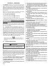
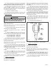
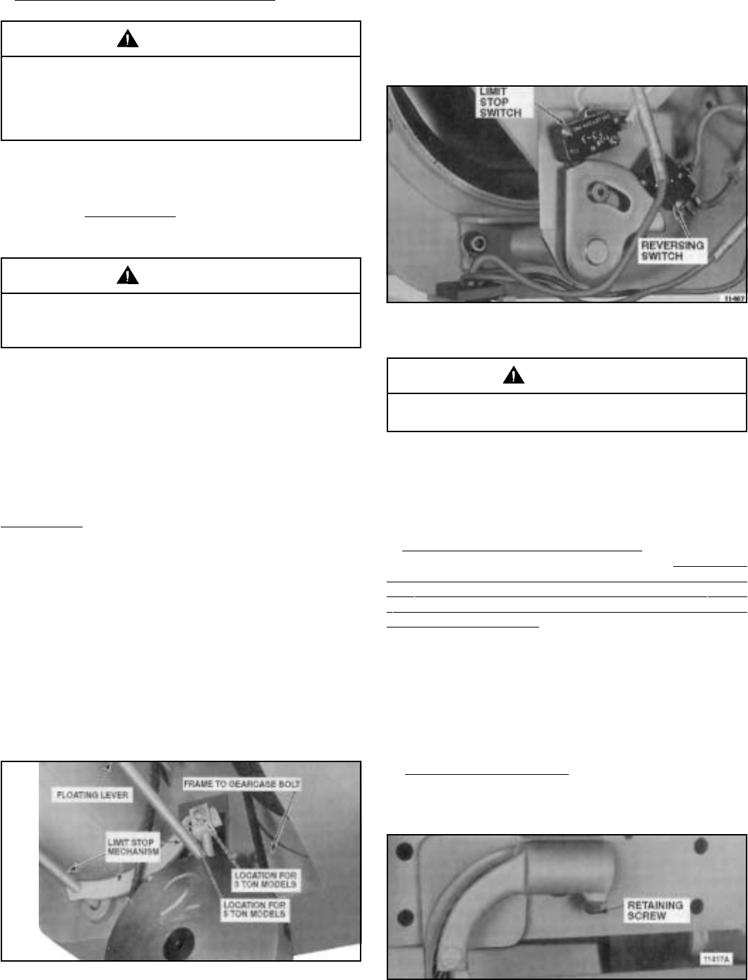
When floating rod is raised, stop switch is actuated first and
then the reversing switch is actuated (Figure 2-3). Stop switch
stops hoist. Reversing switch lowers hook block in case of
floating rod over-travel. If limit switch does not function in this
manner, refer to trouble shooting chart Section Vl for possible
remedy.
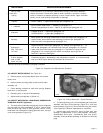
Figure 2-2. Limit Stop Mechanism
Being Tripped By Lower Block.
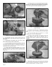
Figure 2-3. Electrical Compartment Cover Removed
Showing Limit Switch and Reversing Switch Arrangement.
Do not attempt to make above test with hook in a
high position near hoist.
WARNING
(2) A screw-type upper and lower limit switch is provided
optionally when both upper and lower limit stops are required
(Figure 7-2). This switch is adjustable and must be adjusted,
at time hoist is installed, to desired high and low limits of
lower block travel. Refer to Section Vll.
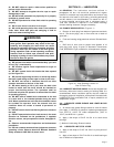
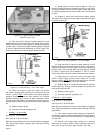
d. Check Lower Block and Hoisting Cable. Depress
ââ
ââ
â push
button and run lower block to its lowest position. No less than
two wraps shall remain on the drum with the loaded hook in
its lowest position, unless hoist is equipped with a lower limit
switch in which case no less than one and one half wraps
shall remain on the drum. Also check to see that lower block
and rope does not twist excessively. If it does twist to the
extent that two ropes rub against each other, disengage rope
from the frame anchor and twist rope four or five turns in a
direction opposite to that which the block turns. Reconnect
rope to anchor (Figure 2-4), holding firmly to eliminate rope
twisting back to its original position. Operate hoist up and
down a few times. If lower block still rotates, repeat process
until twisting is corrected.
e. Lubricate Hoisting Cable. For longer cable life, it is
recommended that the cable be lubricated at time of
installation by applying a Chain and Cable Fluid as outlined
in Section IV, paragraph 4-3.
Figure 2-4. Rope End Anchor.
11403