


Page 13
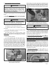
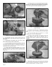
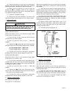
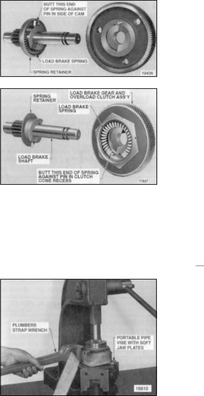
(4) The brake spring must be pre-loaded at assembly to
a torque of from 10 to 14 lb.-ft. This is accomplished using a
plumber’s strap wrench to wind (rotate) load brake gear to
set up spring (Figure 5-10) while pressing brake flange into
place using an arbor press. Clamp pinion end of shaft into a
portable vise to keep brake from rotating in press. Use brass
or copper jaw plates on vise to protect pinion gear teeth.
Wind gear counterclockwise (viewing brake from flange end)
with strap wrench and press down on flange until snap ring
groove in shaft is exposed allowing snap ring to be installed.
Use extreme care not to over wind spring as yield will result
and final spring torque will be reduced. Do not wind gear
beyond point necessary to install snap ring in groove.
h. Install gearing and load brake assembly in gearcase in
reverse order of disassembly. Be certain roller thrust bearings
are installed at both ends of intermediate gear shaft as shown
in Figure 5-4 and that thrust washers are properly installed at
both ends of load brake shaft as noted below:
(1) A steel thrust washer with 5/8" I.D. must be installed
on the brake flange end (end opposite pinion) of load brake
as shown in Figure 5-5.
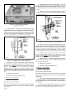
(2) A bronze thrust washer with a lug on one side goes
on pinion end of load brake shaft and it must be installed so
that its lug engages the special slot located on the spot face
surrounding the load brake bearing bore inside gearcase
cover. Use heavy grease to hold it in place on cover as cover
is installed.
On hoists with 18 or 20 tooth load brake pinion, an 11/
16" I.D. steel thrust washer is installed between pinion
and bronze thrust washer.
j. At completion of reassembly of gearing and load brake in
gearcase, refill gearcase to proper level using correct grade
of oil, as outlined in Section IV — LUBRICATION.
k. For hoists equipped with an overload clutch (optional)
which has been functioning properly, visually inspect clutch
adjusting nut and spring washer for signs of damage or
looseness. With a small hex allen wrench, make certain two
set screws in adjusting nut are tight. DO NOT TURN
ADJUSTING NUT OR DISASSEMBLE CLUTCH. If spring
washer, adjusting nut or gear is loose or damaged, or the
clutch did not function properly before disassembly of hoist
for inspection, consult the nearest YALE Authorized Repair
Station for repair or adjustment.
5-7. INSPECT ROPE DRUM AND SHAFT.
a. To remove drum, remove wire rope, electrical
compartment cover and electrical panel assembly (Figure
9-1) and gearing and load brake assembly (paragraph 5-6).
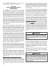
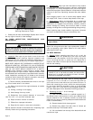
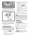
b. Remove four hex socket head bolts securing gearcase to
cover. Three bolts are accessible from inside frame (Figure
2-2, Section II) and the fourth is accessible from electrical
end of frame thru special access hole using a socket hex key
wrench with an extension (Figure 5-11). With bolts removed,
pry assembled gearcase and motor from frame. Exercise
caution so that gearcase and motor assembly does not fall
as it comes free of frame. This disassembly operation is not
recommended with hoist suspended. Drum will remain in frame
and can be lifted from drum shaft. To remove shaft, remove
internal retaining ring from bearing bore in frame.
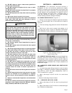
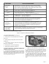
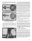
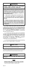
(1) Before installing spring in its retainer (Figure 5-9), apply
a good grade of ball bearing grease to inside of retainer.
Spring must be positioned exactly as illustrated, butted against
pin at side of cam.
LOAD BRAKE — STANDARD
LOAD BRAKE — OVERLOAD CLUTCH
Figure 5-9. Load Brake Gear Removed From
Load Brake Showing Load Brake Spring.
(2) When installing pawl and ratchet assembly on load
brake shaft, be certain that teeth on ratchet face are in the
same direction as shown in Figure 5-8. The ratchet assembly
should rotate freely when turned counterclockwise and the
pawl should engage ratchet teeth when unit is turned
clockwise.
(3) When installing brake flange, position it with chamfer
facing friction disc (Figure 5-7).
Figure 5-10. Winding Load Brake Gear Using a Strap
Wrench to Set Up Load Brake Spring.