


Page 21
SECTION Vll — ADJUSTMENTS
7-1. MECHANICAL LOAD BRAKE. The mechanical load
brake on Series 800 YALE hoists is a pawl and ratchet “Weston”
type automatic brake. The brake is not adjustable and requires
only periodic inspection and occasional replacement of the
friction washers.
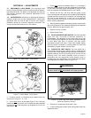
7-2. MOTOR BRAKE. Instructions for adjusting the brake are
inside the brake cover and are repeated below. Check brake
adjustment after the first 30 days of service and regularly
thereafter during the six-month inspection procedure. Two
versions of the motor brake occur in this manual.
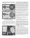
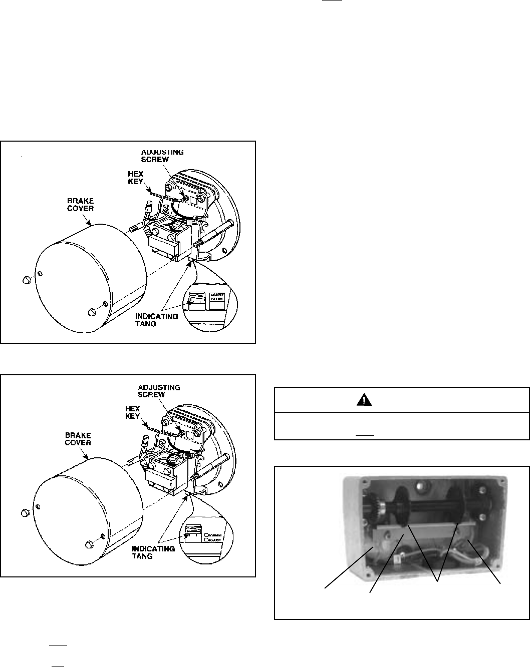
Figure 7-1A. Motor Brake - Later Version.
Figure 7-1. Motor Brake - Early Version.
a. Examine position of indicating tang located below the
solenoid coil (Figure 7-1 or 7-1A).
b. On the
later version of the brake (Figure 7-1A), if the tang
is below the line by more than 1/8", the brake should be adjusted
to bring the top of the tang back up alongside the line on the
adjust label.
c. On the early version of the brake (Figure 7-1), if the tang is
below the midway position of the two adjustment points shown
on the brake, the brake should be adjusted to bring the tang
back up alongside the NORMAL position on the brake.
d. Remove the hex key (1/8" size) from the holster on the
cover mounting stud and carefully turn the ADJUSTING SCREW
(located above the solenoid coil) clockwise. The indicating tang
will move a large distance for a small turn of the adjusting
screw, therefore turn the screw no more than one quarter turn
before checking adjustment.
e. After adjustment operate the brake by hand to assure brake
disc running clearance. The outboard brake pad should separate
from the brake disc by approximately .010".
f. Replace hex key in holster.
g Replace brake cover.
7-3. BLOCK OPERATED LIMIT SWITCH. The block operated
upper limit stop, furnished as standard equipment, is
nonadjustable and designed to stop lower block at its high
point of travel to guard against over-travel with possible damage
to hoist. When high point is reached, limit stop switch
automatically stops hook travel. If hook drifts upward slightly
after stop switch is actuated, a reversing switch will close and
automatically reverse direction of hook travel.
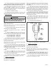
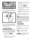
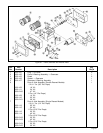
7-4. SCREW-TYPE LIMIT SWITCH. This limit switch has a
rotary screw driven by a gear reduction which is coupled to the
end of the drum shaft. Adjustment discs operate the contacts of
separate switches; one for the hoisting circuit and one for the
lowering circuit. The switch assembly must be wired in
accordance with the appropriate wiring diagram, which is
packaged with hoist. Adjustment of this screw-type limit switch
is accomplished as follows: (Refer to Figure 7-2).
Before attempting actual adjustments, be certain main
power switch is OFF and locked in the open position.
WARNING
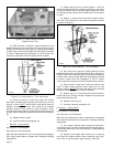
Figure 7-2. Screw-Type Limit Switch Adjustment.
(Wires not Shown for Clarity.)
a. Remove four screws and lift off switch cover.
b. Loosen locking plate screws. Slide locking plate away from
adjustment discs.
12758B
LOCKING
PLATE
SWITCH
SWITCH
ADJUSTMENT
DISCS
12759
12759C