


Page 28
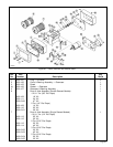
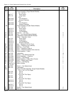
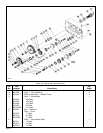
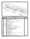
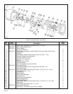
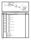
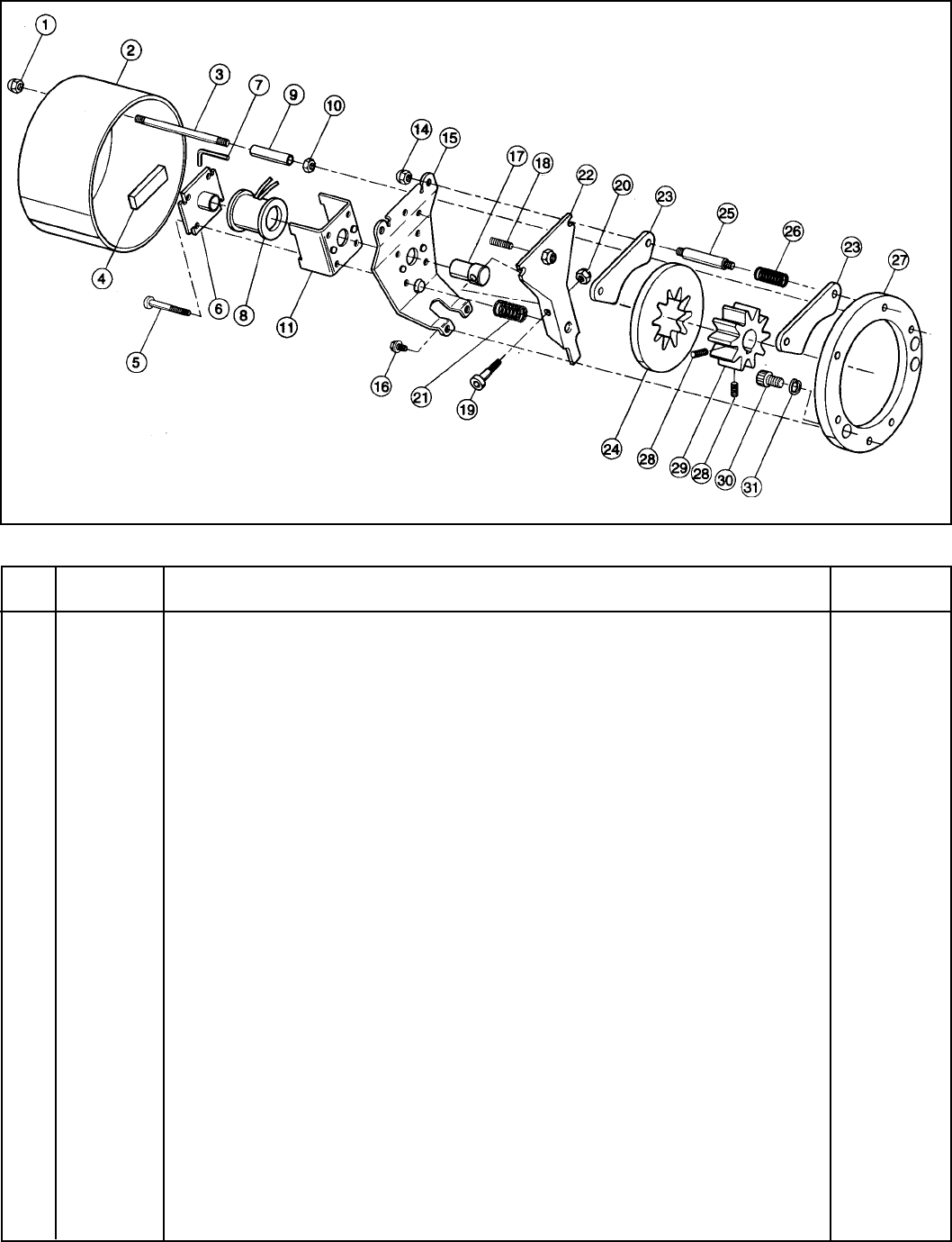
Figure 9-3. Hoist Motor Brake - Later Version.
Ref. Part Qty.
No. Number Description Req’d.
800-2401 Motor Brake Assembly (Includes Ref. Nos. 1 thru 31) 1
1 * Acorn Nut - Plated (#10-32) 2
2 800-2402 Brake Cover Assembly (Includes Brake Cover and Label Inside Cover) 1
3 * Cover Stud 2
4 * Gasket 1
5 * Phillips Pan Head Self Tapping Screw - Plated (#10-32 x 1-3/4) 4
6 * Solenoid Frame Cover Assembly 1
7 * Hex Key (1/8 - 3/4 x 2) 1
8 800-2410† Solenoid Coil Assembly 1
9 * Tubing 3
10 * Hex Nut - Plated (#10-32) 2
11 800-2411 Solenoid Frame 1
14 * Hex Head Self Locking Nut - Plated (#10-32) 2
15 800-2403 Solenoid Support 1
16 * Hex Washer Head Thread Forming Screw - Plated (#10-32 x 1/4) 2
17 * Solenoid Plunger 1
18 * Hex Socket Head Set Screw - Oval Point (1/4-28 x 1) 1
19 * Hex Socket Shoulder Screw (#10-24 x 1)** 1
20 * Hex Head Self Locking Nut - Plated (#10-24)** 1
21 * Brake Spring (Use Red Spring Only) 1
22 * Brake Lever Assembly 1
23 * Pressure Pad 2
24 Brake Disc (Non-asbestos) 1
25 * Brake Support Stud 2
26 * Separating Spring 2
27 800-2404 Brake Mounting Plate 1
28 * Hex Socket Head Self Locking Set Screw - Cup Point (1/4-20 x 3/8) 2
29 * Brake Hub 1
30 * Hex Socket Head Screw (3/8-16 x 3/4) 2
31 Lock Washer (3/8) 2
Wire Nuts — Not Shown (No. 22 thru 14 AWG) 4
* Not available as individual parts. See replacement kits listed below.
** Later models have a hex socket head screw (1/4-20 x 1-1/2) with a hex head self locking nut - plated (1/4-20).
Kits include quantities shown above.
12756H