


Page 4
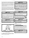
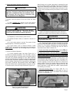
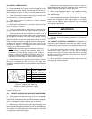
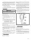
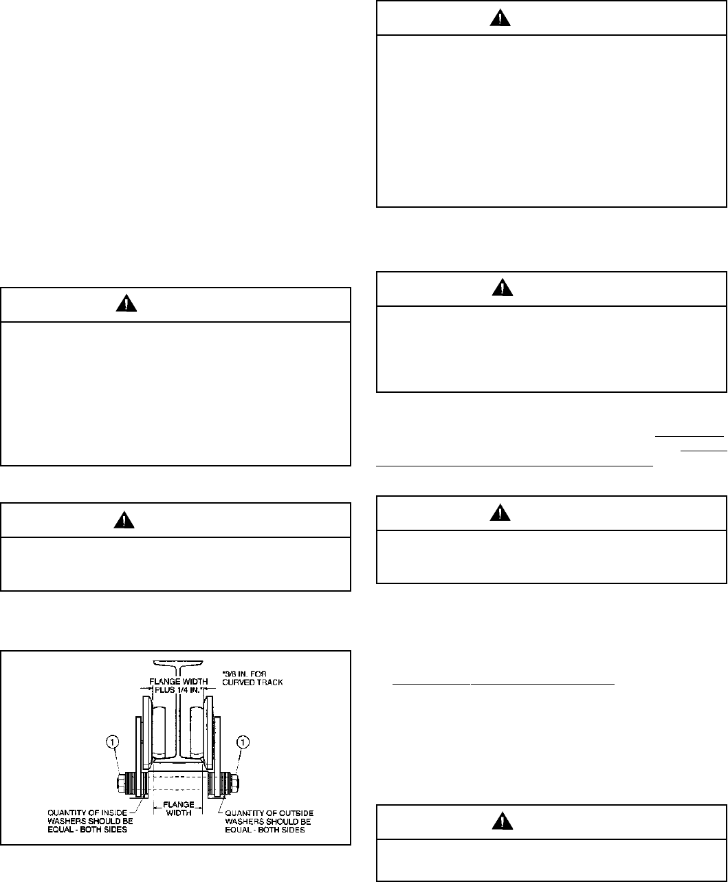
For trolleys which are to be mounted along the span of a
beam not having open ends, measure exact width of beam
flange and assemble trolley to hoist so that spacing between
wheel flanges is 1/4" (see Figure 2-1) greater than beam
width (3/8" if beam has curves). This is accomplished by
rearranging the spacer washers on the bolts connecting trolley
side plates to hoist mounting lug. If trolley is shipped separate
from hoist, see instruction sheets furnished with trolley for
orientation and installation.
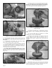
When proper spacing has been determined, loosen mounting
nuts (item 1, Figure 2-1) to allow trolley wheels to spread far
enough to pass over edges of beam flange. (Some installations
may require complete removal of one trolley side plate.) Using
adequate equipment, carefully lift the hoist and trolley so the
wheel treads will rest on the lower beam flange. Replace side
plate and washers if removed for installation. Replace
suspension stud nuts.
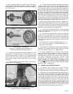
Figure 2-1. Sectional View of Trolley showing proper wheel
and washer spacing.
2-3. CONNECTING HOIST TO ELECTRICAL SERVICE.
Electrical service to the hoist may be power cable or a guarded
system having sliding shoe collectors.
Recheck spacer washers to make certain that the number
of washers between the side plate and hoist suspension lug
are equal, and also the number on the outside of each side
plate are equal. The suspension stud nuts should only be
snugged up on the lockwashers until a load has been
applied on the hook. A partial load (approx. 25% rated hoist
load) placed on the hook will properly seat hoist in the
trolley. Tighten suspension stud nuts only after hoist has
been properly seated in the trolley.
CAUTION
a. Follow National, State and Local Electrical Codes
when providing electrical service to the hoist.
b. Make electrical connections using the appropriate wiring
diagrams furnished with the hoist. All electrical connections,
including connections to collectors or power cord, shall be
made only by qualified journeymen electricians.
c. When trolley is shipped separate from hoist, see special
instructions furnished with trolley for orientation and
installation.
2-4.PRE-OPERATION CHECKS.
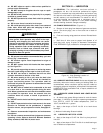
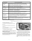
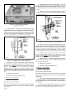
a. Check Oil Level and Grease Fittings. The gearcase has
been filled with oil to the proper level and grease points for
lower and upper sheaves have been lubricated at the factory.
However, this should be checked before operating hoist. Check
oil level by removing oil level plug with hoist in a level position.
Oil level should be at the bottom edge of the plug hole. If not,
add oil as specified in Section IV. Grease fittings in lower and
upper sheave pins should show evidence of grease.
208/230/460V single speed motors are reconnectable at
the motor. See motor nameplate. Transformer may be
reconnected for 200/230/460/575V. See transformer. Check
with wiring diagram to make certain that motor, transformer
and brake leads are properly connected.
CAUTION
Be certain that electrical power supply is off and locked
in the open position before attempting any electrical
connections to the hoist. This equipment must be
effectively grounded according to the National Electric
Code, or other applicable codes. If the grounding
method used is through the trolley wheels, then each
section of track must be grounded by metal-to-metal
connection to the building ground. Certain
environments may prevent proper grounding by this
means. In this case a separate grounding conductor
should be provided.
WARNING
Mounting of the hoist-trolley unit on the monorail and
final pre-operation inspection shall be performed only
by qualified persons properly supervised.
WARNING
The green wire provided in the power supply cable
(when furnished) is a grounding wire and must be
connected to a proper ground.
WARNING
Overfilling of the gearcase may result in the excess fluid
being expelled through the breather.
CAUTION
11207A