


Page 12
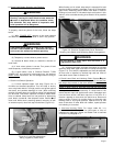
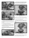
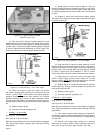
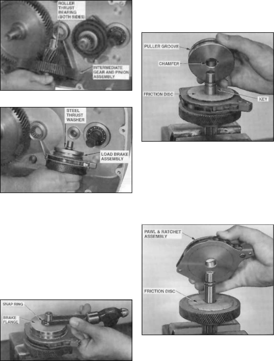
Figure 5-4. Removing Intermediate Gear and
Pinion Assembly.
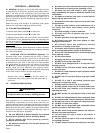
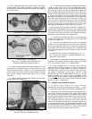
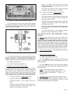
Figure 5-5. Removed Load Brake Assembly.
d. To disassemble drum gear, remove external snap ring
from splined shaft, using heavy-duty snap ring pliers, and
pull off gear.
e. To disassemble intermediate gear and pinion, press
pinion shaft from gear using an arbor press.
f. It is recommended that load brake assembly be returned
to an Authorized Repair Station for inspection and repair. If it
is necessary that you make your own inspection and repair,
instructions below must be followed:
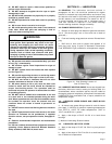
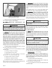
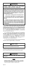
(1) Place load brake assembly, flange up, in a vise
equipped with brass or copper jaw plates to protect pinion
gear teeth. Remove snap ring from end of load brake shaft
(Figure 5-6).
Figure 5-6. Remove Snap Ring From Load Brake Shaft.
10333
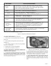
(2) Using a puller tool, remove brake flange from shaft.
A groove is provided around outer diameter for this purpose.
See Figure 5-7. Remove key from shaft and lift off 2 friction
discs, and the pawl and ratchet assembly (Figure 5-8).
Figure 5-7. View Showing Load Brake
Flange Removed.
(3) Remove load brake gear. If replacement of spring,
spring retainer or cam is necessary, press off shaft (Figure
5-9).
(4) The load brake pawl and ratchet is a riveted
assembly and is not to be disassembled.
(5) Clean all parts thoroughly and inspect for wear and
damage. Replace all parts that are excessively worn or
damaged. Hard surface or glazed friction discs should be
replaced.
Figure 5-8. Removing Pawl and Ratchet Assembly
From Load Brake Shaft.
g. Reassemble gearing and load brake parts following
reverse procedure of disassembly. In assembling load brake,
observe assembly steps (1) through (4) below:
11422
11421
10334
10335A