


Page 3
This brake requires periodic adjustment.
SECTION II — INSTALLATION
2-1.GENERAL. YALE electric hoists are lubricated and tested
before being shipped from the factory. To place hoist in service,
attach to a suitable suspension (paragraph 2-2), connect to
electrical service (paragraph 2-3) and perform pre-operation
tests and checks (paragraph 2-4).
2-2.SUSPENDING HOIST. The hoist may be suspended in a
fixed location servicing only the area directly below the hoist
(Lug Mounted) or the hoist may be attached to a moveable
trolley or trolleys which in turn may be mounted on an l-beam
attached to a building or crane, servicing a larger area (Trolley
Mounted).
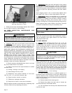
a. Lug Mounted hoists attach to adequate supports welded
or bolted to a building or other structure. The supporting
structure must have sufficient strength with appropriate safety
factor, to support the weight of the hoist and rated load as
well as other loads to which the supporting structure may be
subjected.
Steel angles or plates used to suspend hoist should be spaced
as close to the hoist suspension lug as possible. Mounting
bolts or threaded studs, attaching hoist to mounting structure,
shall have a diameter not less than recommended by
manufacturer and material equivalent to ASTM A 325. Make
certain that mounting bolts or studs are long enough so that
the threads do not engage the mounting support and that
mounting bolts or studs are secured with nuts and
lockwashers, self-locking nuts or cross bolting, if unthreaded.
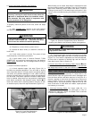
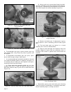
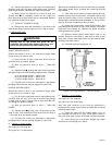
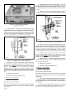
b. Trolley Mounted hoists are attached to moveable trolleys. If
the hoist is mounted on an existing trolley, a qualified person
shall determine that the trolley and its supporting structure
are adequate to support the rated load and weight of the
hoist. Hoist/trolley units may be shipped from the factory with
trolley packaged separately. If the trolley can be installed
directly over the end of the supporting beam, assemble trolley
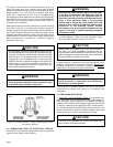
to hoist. Be certain that the spacing between wheel flanges,
after assembly, is 1/4" greater than exact width of beam
flange. (See Figure 2-1 below and instruction sheet furnished
with trolley.) Using proper equipment, carefully lift trolley and
hoist and install on end of beam.
SECTION I — GENERAL DESCRIPTION
1-1. GENERAL. YALE electric hoists are precision built wire
rope and drum type hoists which are made in five rated load
sizes (1/2, 1, 2, 3 and 5 tons) with various lifts, lifting speeds
and electrical service. Equipped with an integrally welded
mounting lug, they are designed to be rigidly attached to an
overhead structure or mounted on YALE rigid mount trolleys
for operation on runway beams. On certain models optional
base mounting or other supporting methods may be obtained.
For full information apply to factory at Muskegon, Michigan
49443.
NOTICE
YALE hoists are available with an optional built-in
mechanical overload clutch. Hoists having this device
are identified with words WEIGHT WATCHER on the
hoist.
The WEIGHT WATCHER overload clutch permits operation of
your hoist within its rated load and helps prevent lifting of
excessive loads which could cause permanent deformation
of a properly maintained hoist or trolley.
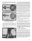
1-2. BASIC CONSTRUCTION. All models are of the same
basic construction and consist of a rugged welded steel frame
which houses a lifting drum and serves as the suspension for
carrying the entire hoist load. A mounting lug, for attaching
the hoist to a trolley or overhead support, is located on top of
the frame. An aluminum alloy gearcase and cover, attached
to one end of frame, houses a three-reduction gear train and
a mechanical load brake. An electric driving motor with disc-
type motor brake is located beside the frame, face mounted
on the back of the gearcase. Electrical system components,
located on the end of the frame (opposite gearcase end) and
enclosed by a steel cover, control operation and rotating
direction of a driving motor. A hoisting rope and an enclosed
lower block assembly are used for lifting loads. An upper limit
stop is used to limit travel of the lower block in the raising
direction, to protect hoist from damage. A push button control
station, for operating the hoist, is suspended from the electrical
compartment.
1-3. DIFFERENCES BETWEEN MODELS. The main
differences between models are in rope reeving and frame
size as described below.
a.
Rope Reeving. There are four types of rope reeving used:
Two parts of rope single reeved, four parts of rope single
reeved, six parts of rope single reeved and two parts of rope
double reeved. Single reeved hoists have one end of the
rope anchored to the drum, whereas, double reeved hoists
have both ends anchored to the drum. On single reeved
models, the lower block travels sideways as rope winds on
drum, double reeved models offer true vertical lift. For
illustrations, refer to Section V, paragraph 5-9, “Rope Reeving”
instructions.
b. Frame Size. Length of frame furnished is dependent on
hoist capacity and lift. Four frame lengths are used; short
frame, long frame, first and second extensions. Short frame
hoists have a rope drum flange to flange distance of
approximately 9-3/4", whereas this distance on a long frame
hoist is approximately 16-3/4". First extension frame hoists
have a flange to flange distance of 22-15/16" and second
extensions have 35-3/8".
c. Motor Brake. Hoists are equipped with a disc brake mounted
on the motor end bell and operated by a short stroke solenoid.
Before attempting installation of hoist or trolley, the
main power switch must be locked in the open position
(off).
WARNING
DO NOT use small holes for attaching this hoist unless
rated load on lower block is 1 (one) ton (2000 Ibs.) or
less.
WARNING
Design and installation of hoist support shall be
performed only by qualified persons.
WARNING