


Page 22
9-2. INDEX OF EXPLODED VIEW PARTS ILLUSTRATIONS
Figure No. Title Page No.
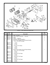
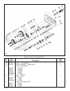
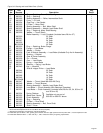
9-1 Frame, Gearcase and External Parts ...........................................................................................................23
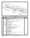
9-2 Gearing and Load Brake Parts .....................................................................................................................26
9-3 Hoist Motor Brake - Later Version .................................................................................................................28
9-4 Hoist Motor Brake - Early Version............................................................................................ ..................30
9-5 Three Phase Motor Assembly.......................................................................................................................32
9-6 Upper Limit Switch Parts...............................................................................................................................33
9-7 Electrical Control Equipment.........................................................................................................................34
9-8 Push Button Station Assembly and Conductor Cable (Single Speed) ........................................................35
9-9 Push Button Station Assembly and Conductor Cable (Two Speed) - Later Version...................................36
9-10 Push Button Station Assembly and Conductor Cable (Two Speed) - Early Version...................................38
9-11 Lower Block Assembly — 2 parts rope, single reeved ................................................................................40
9-12 Lower Block Assembly — 2 part double reeved...........................................................................................41
9-13 Upper and Lower Block Parts (3 & 5 Ton) ....................................................................................................42
9-14 Screw-Type Limit Switch Parts......................................................................................................................43
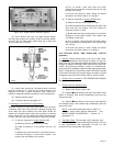
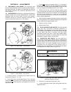
Provide a light film of NLGI No. 2 grease on bevel gear of limit
switch.
7-5. OVERLOAD CLUTCH ADJUSTMENT. When properly
adjusted, the overload device is designed so that the hoist will
lift its full rated load but will refuse to lift an excessive overload.
The overload clutch is not externally adjustable. It is necessary
to remove the overload clutch assembly from the hoist for proper
adjustment. Therefore, it is strongly recommended that when
adjustment and/or replacement parts are required, a SHAWBOX
Authorized Repair Station be contacted. Consult your SHAWBOX
Distributor for nearest Repair Station.
SECTION VIII — WIRING DIAGRAMS
Wiring diagrams for SHAWBOX electric hoists have been omitted
from this book because of many possible variations. This is due
to different currents and types of electrical components used in
their construction. A print of the correct wiring diagram for each
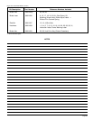
The numbers assigned to the parts of our various assemblies in our parts lists are not the part numbers used in
manufacturing the part. They are identification numbers, that when given with the model number, permit us to
identify, select or manufacture, and ship the correct part needed.
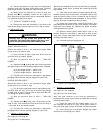
Check limit switch operation carefully, without load,
before placing hoist in service. If misadjusted, SEVERE
DAMAGE AND/OR A DROPPED LOAD COULD RESULT.
Allow 6" for hook drift in both directions. Never allow
less than 1-1/2 complete wraps of rope on drum with
hook in lowest position.
WARNING
hoist is furnished as a separate insert and shipped with hoist.
We suggest you carefully file the wiring diagram with this book
for future reference.
WHEN ORDERING PARTS OR INFORMATION ON THIS
EQUIPMENT, ALWAYS INCLUDE MODEL AND SERIAL
NUMBER ON ORDER.
SECTION IX — PARTS LIST
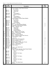
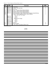
9-1. GENERAL. The parts lists and illustrations in this section
of the manual, cover parts for all standard 800 SHAWBOX
Electric Hoists. A typical hoist is shown as the basis for the
exploded parts illustrations; therefore, certain variations may
occur from the information given. For this reason, always give
the Hoist Serial Number, Catalog Number, Motor Horsepower,
Voltage, Phase, Frequency and Rated Load of Hoist when
ordering parts.
Certain parts of your hoist will, in time, require replacement
under normal wear conditions. It is suggested that these parts
be purchased for your hoist as spares for future use. These
parts are indicated by a (†) symbol at the right side of the parts
reference numbers.
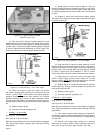
c. Turn proper adjustment disc (right for up, left for down)
toward stitch to reduce hook travel or away from switch to
increase hook travel.
d. Slide locking plate back into position ensuring slots on
adjustment discs are fully engaged, tighten locking plate screws
to 4 in-lbs.
e. Replace cover.
NON-FACTORY AUTHORIZATIONS OR MODIFICATION
OF EQUIPMENT AND USE OF NON-FACTORY REPAIR
PARTS CAN LEAD TO DANGEROUS OPERATION AND
INJURY.
TO AVOID INJURY:
• Do not alter or modify equipment without factory
authorization.
• Do use only factory provided replacement parts.
WARNING